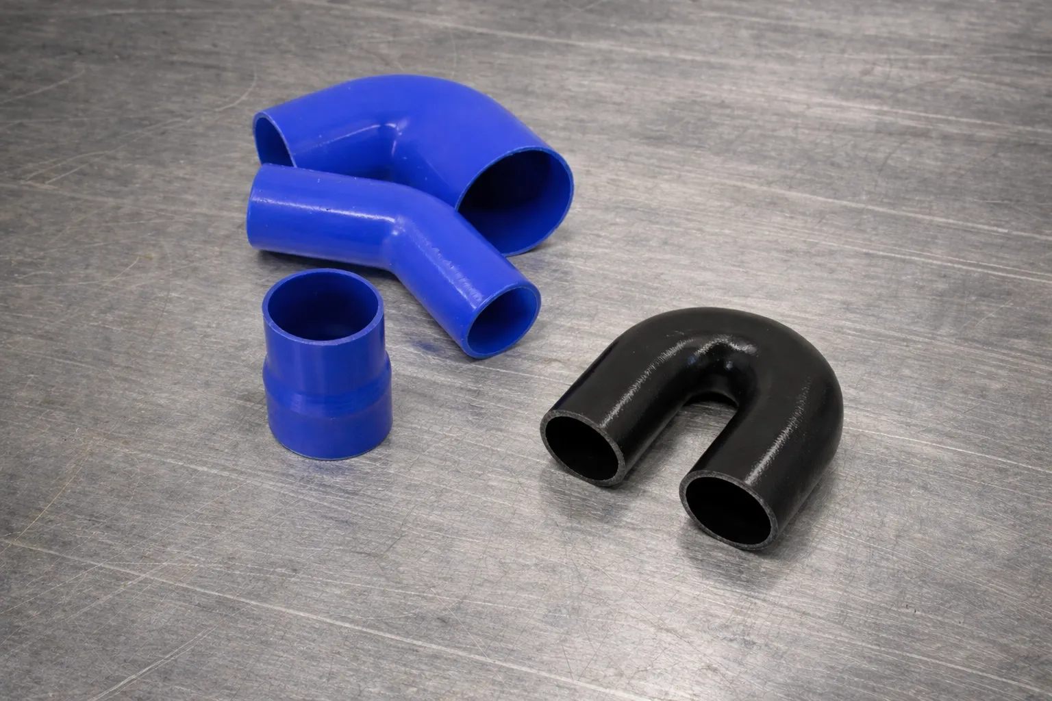
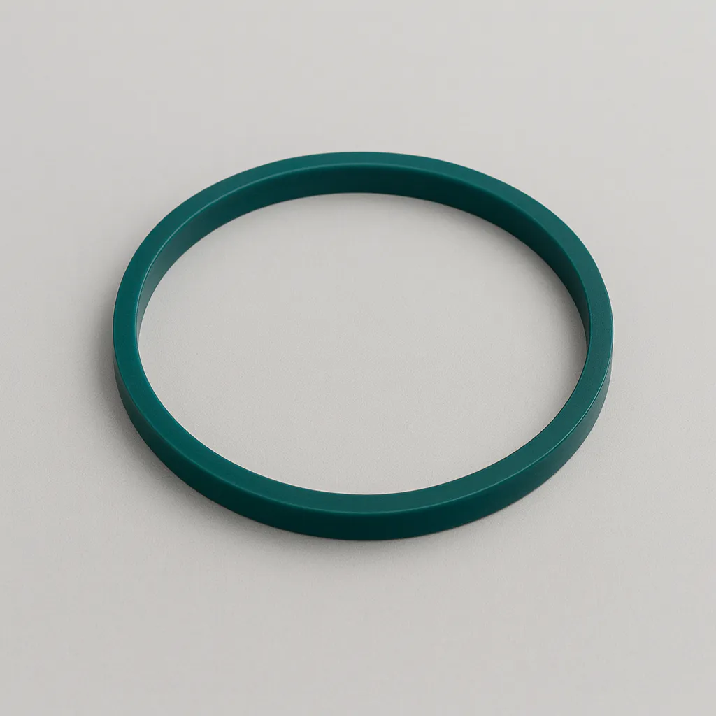
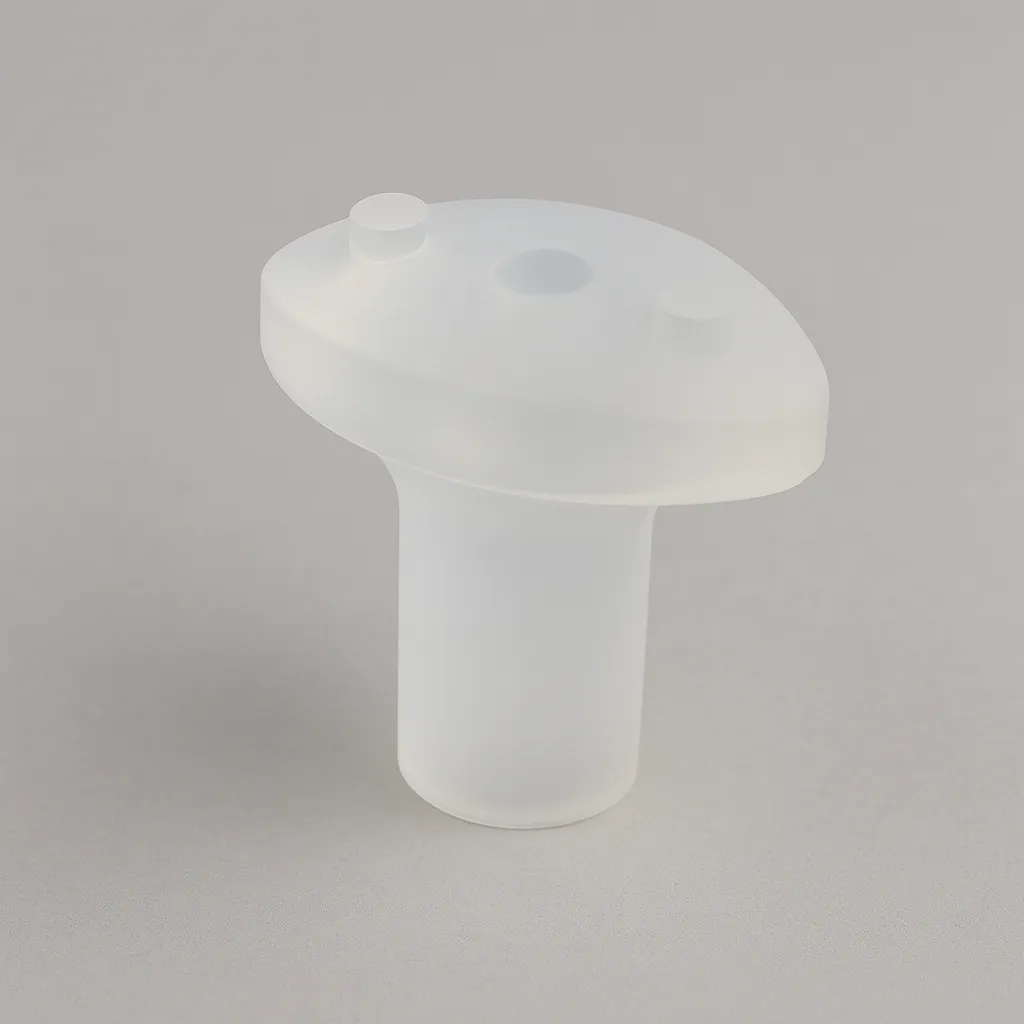
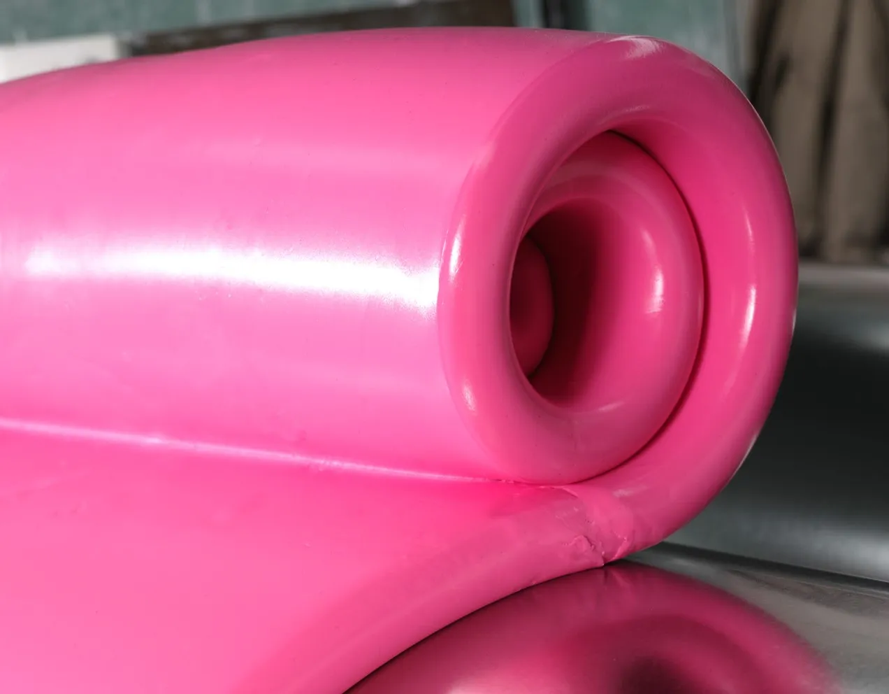
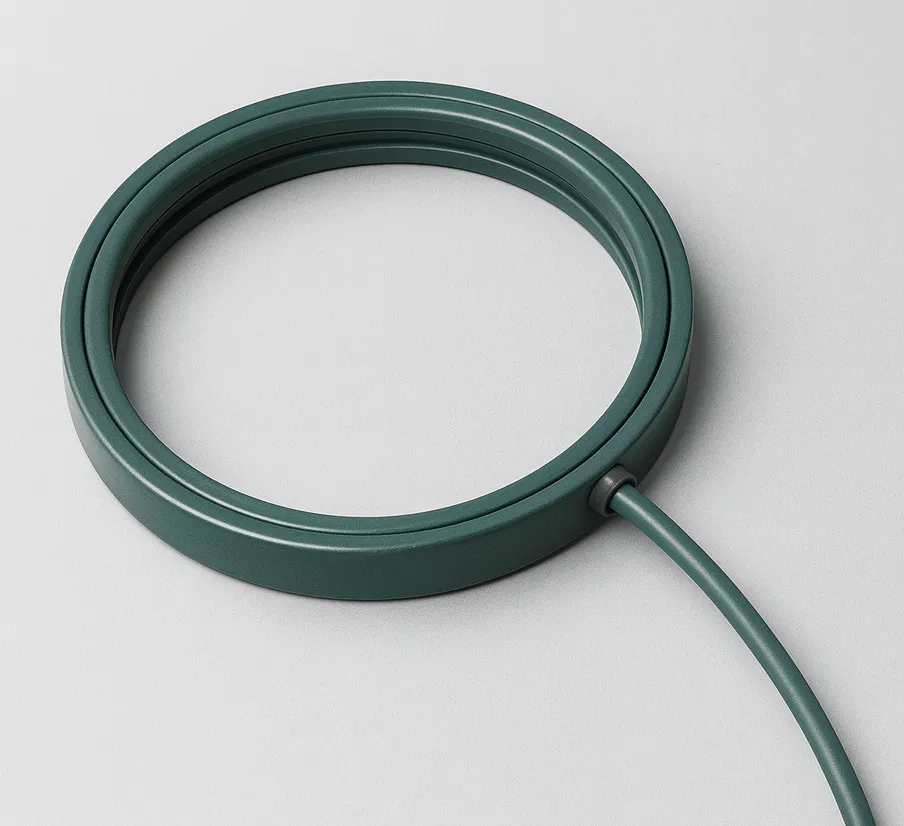
Serie 1 – Silicona a base de peróxido de alta resistencia al desgarro
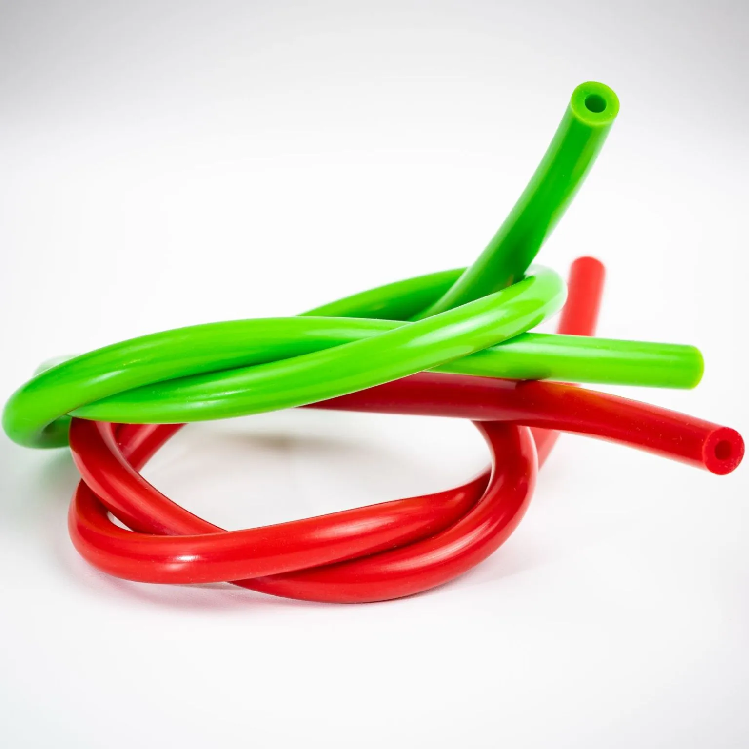
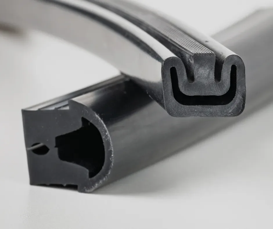
La Serie 1 es una formulación de silicona VMQ catalizada por peróxido, diseñada para aplicaciones industriales exigentes donde se requiere una elevada resistencia al desgarro, buen comportamiento mecánico y estabilidad en servicio continuo. Es apta para procesos de extrusión y moldeo, permitiendo la fabricación de perfiles, tubos, juntas y piezas técnicas sometidas a esfuerzos mecánicos repetidos.
Silicona técnica de alta resistencia al desgarro, catalizada por peróxido y transformable por extrusión o moldeo. Presenta buenas propiedades mecánicas, excelente comportamiento térmico y aptitud para contacto alimentario según formulación.
Dureza Shore A40 – 70
Rango de temperatura-60 °C / 200 °C
Densidad (g/cm³)1.12 – 1.19
Resistencia a la tracción (MPa)6.0 – 8.0
Alargamiento a la rotura (%)500 – 600
Resistencia al desgarro (kN/m)26.0 – 40.0
Tipo de catálisisPeróxido
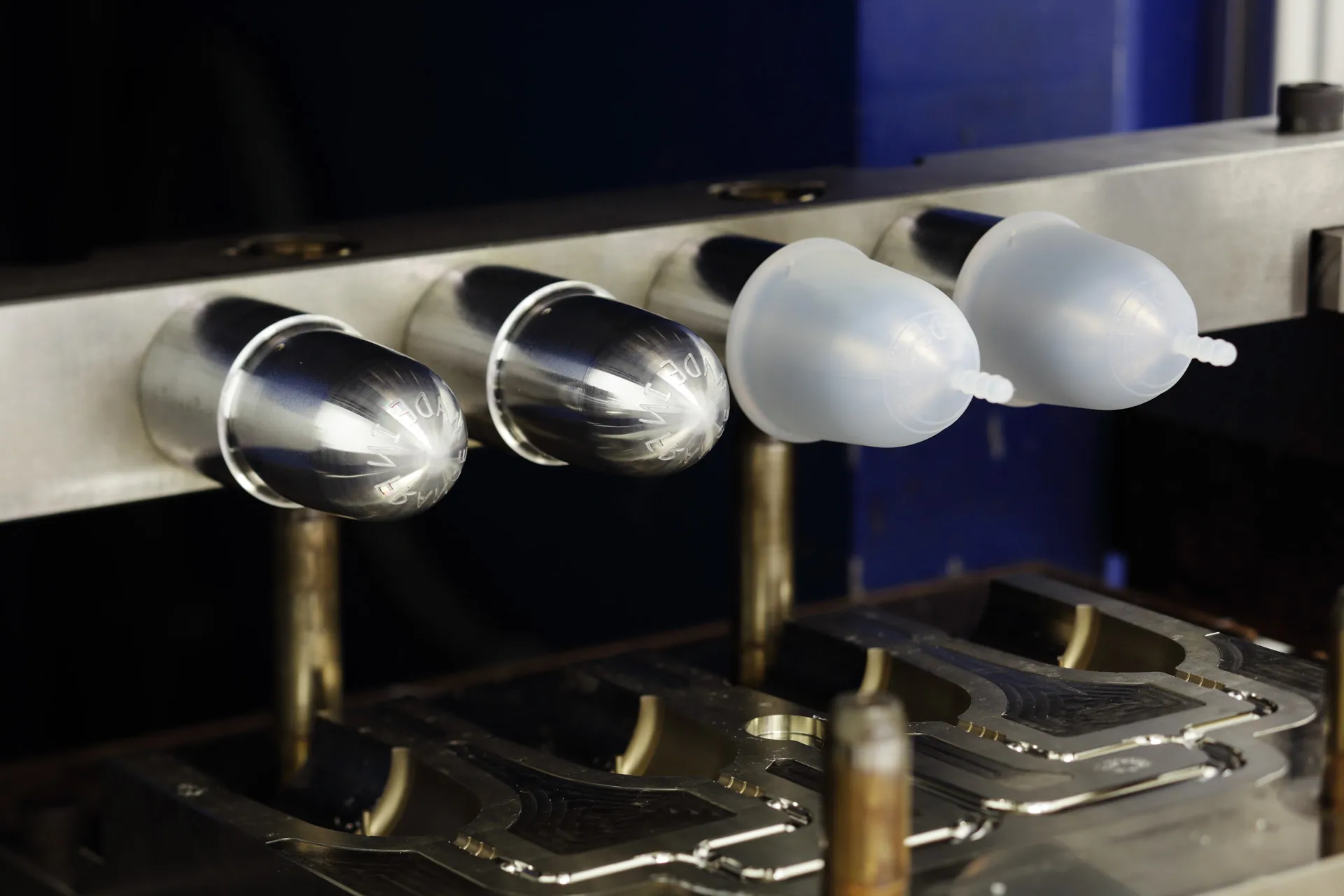
Proceso de transformaciónExtrusión y Moldeo
Color baseNatural / Transparente
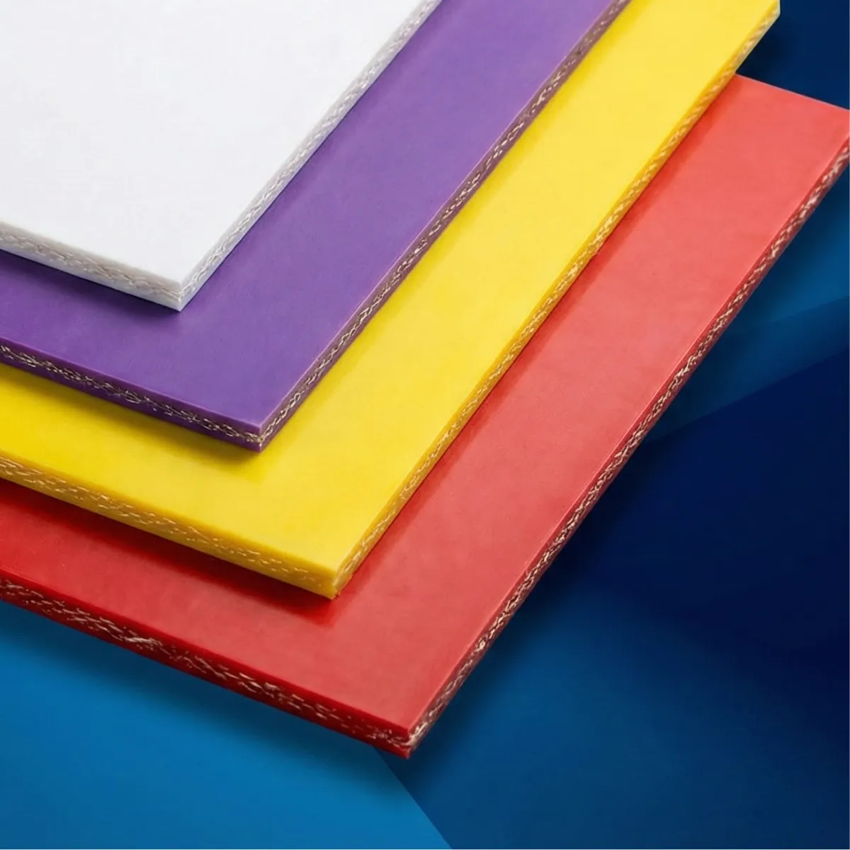
Colores disponiblesVarios colores según muestrario RAL
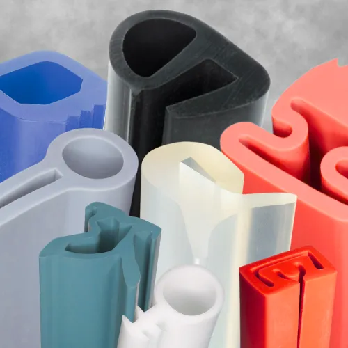
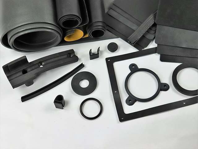
Aplicaciones
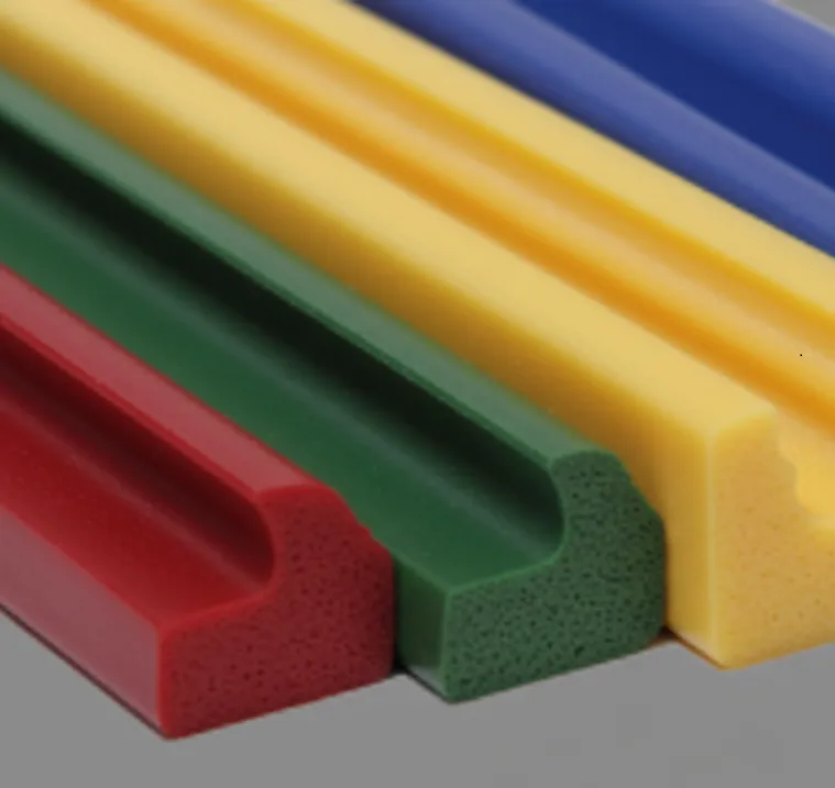
- Juntas hinchables, tubos, perfiles y piezas moldeadas de silicona técnica.
Certificaciones y normas técnicas
- FDA 21 CFR §177.2600
- BfR IX et XV
- CE 1935/2004 (Alimentario según formulación)
- RoHS compliant
- REACH compliant
- NF ISO 7619-1
- NF ISO 37
- NF ISO 34-1
- NF ISO 2781
- ISO 3302 (M2/E1/L2)
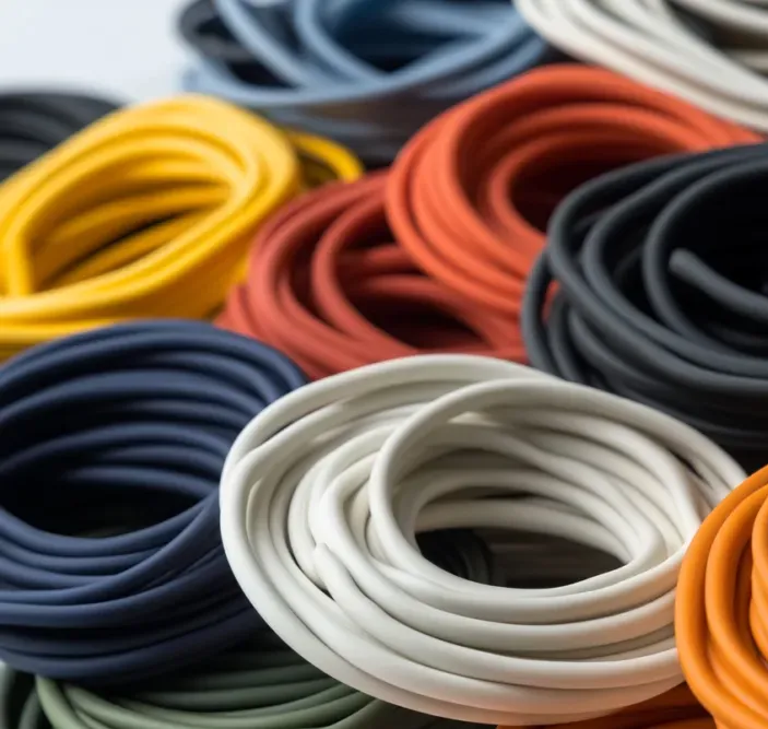
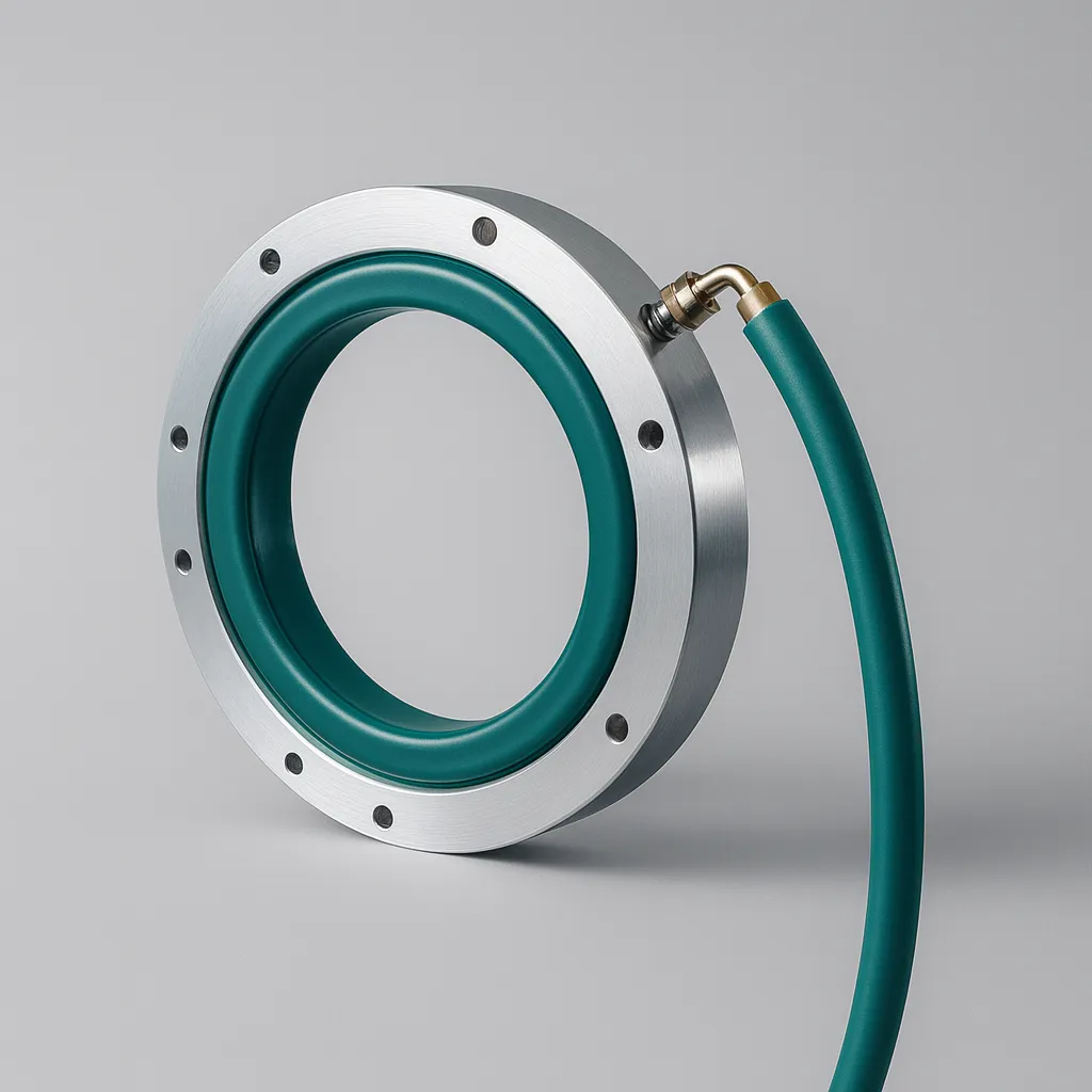
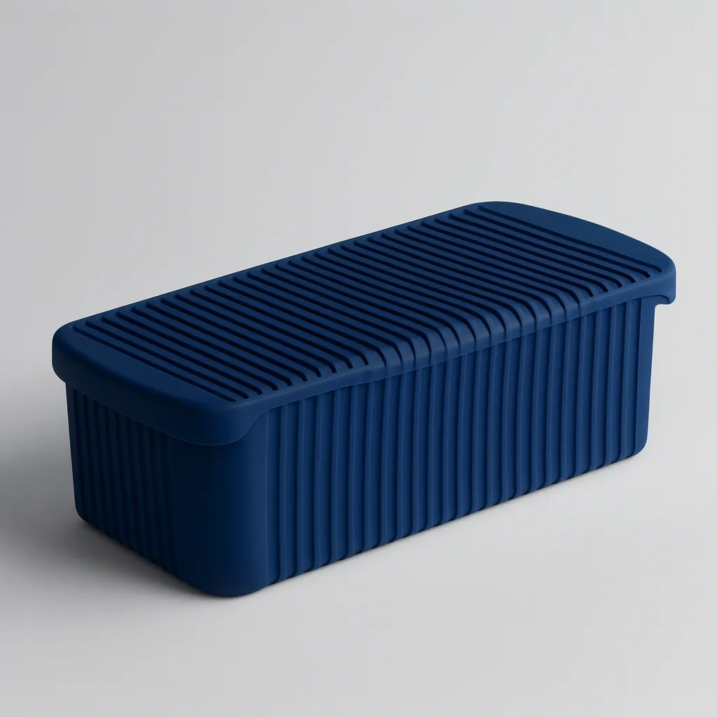
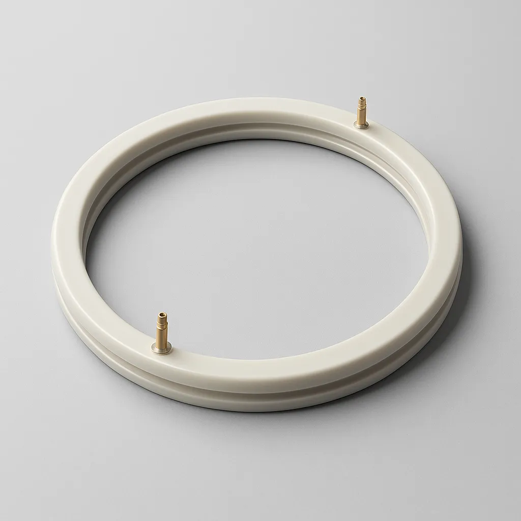
Serie 10 – Silicona platino de alto desgarro para aplicaciones médicas y alimentarias
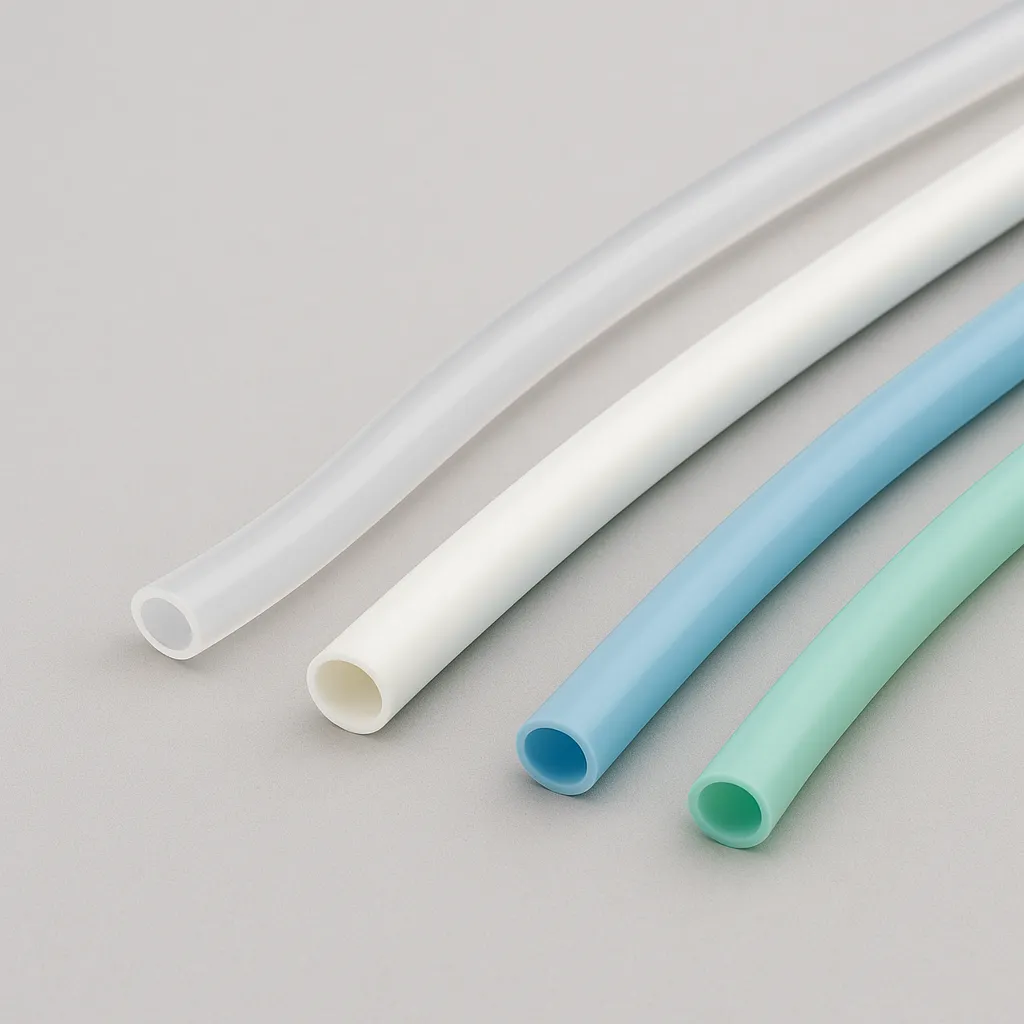
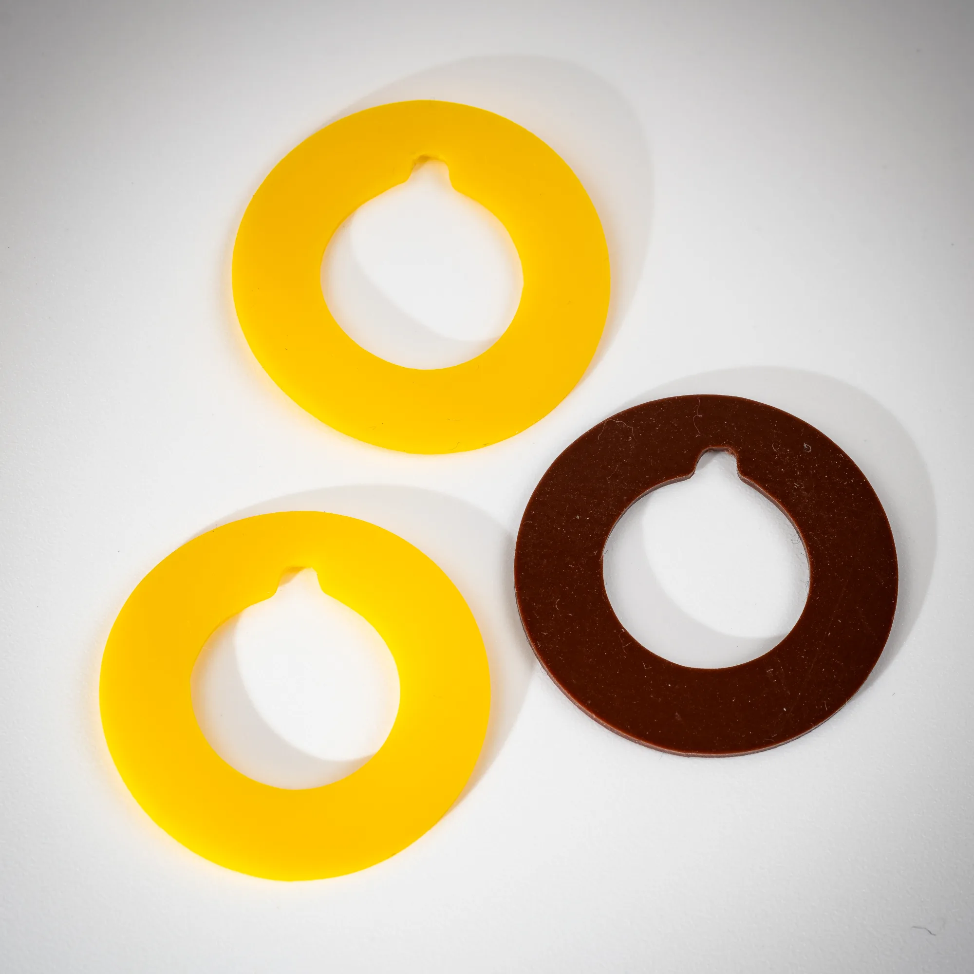
La Serie 10 es una mezcla de silicona catalizada por platino, diseñada para ofrecer una resistencia al desgarro excepcionalmente alta. Es transformable por extrusión y moldeo. Al ser curada al platino, ofrece una pureza superior (sin subproductos de peróxido), lo que la hace ideal para aplicaciones médicas (USP Class VI, ISO 10993) y alimentarias, además de garantizar propiedades mecánicas de alto rendimiento.
Silicona técnica de alta pureza catalizada por platino, transformable por extrusión y moldeo. Ofrece muy buena resistencia al desgarro, excelentes propiedades mecánicas y compatibilidad alimentaria y médica según formulación. Presenta un rango térmico de -60 °C a +200 °C y está disponible en una amplia gama de durezas (40–80 ShA).
Dureza Shore A40 – 80
Rango de temperatura-60 °C / 200 °C
Densidad (g/cm³)1.12 – 1.24
Resistencia a la tracción (MPa)7.0 – 9.0
Alargamiento a la rotura (%)320 – 760
Resistencia al desgarro (kN/m)33.0 – 55.0
Tipo de catálisisPlatino
Proceso de transformaciónExtrusión y Moldeo
Color baseNatural / Transparente
Colores disponiblesColores RAL a petición
Aplicaciones
- Juntas hinchables, tubos, perfiles y piezas moldeadas para aplicaciones industriales, médicas o de contacto alimentario.
Certificaciones y normas técnicas
- FDA 21 CFR §177.2600
- BfR IX et XV
- CE 1935/2004
- ISO 10993 (según formulación)
- USP Class VI
- RoHS compliant
- REACH compliant
- NF ISO 7619-1
- NF ISO 37
- NF ISO 34-1
- NF ISO 2781
- ISO 3302 (M2/E1/L2)
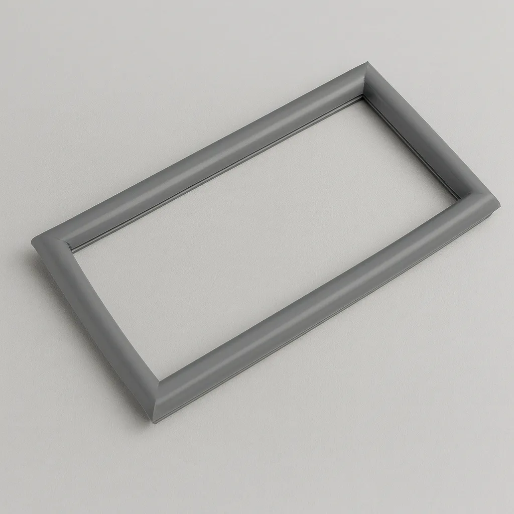
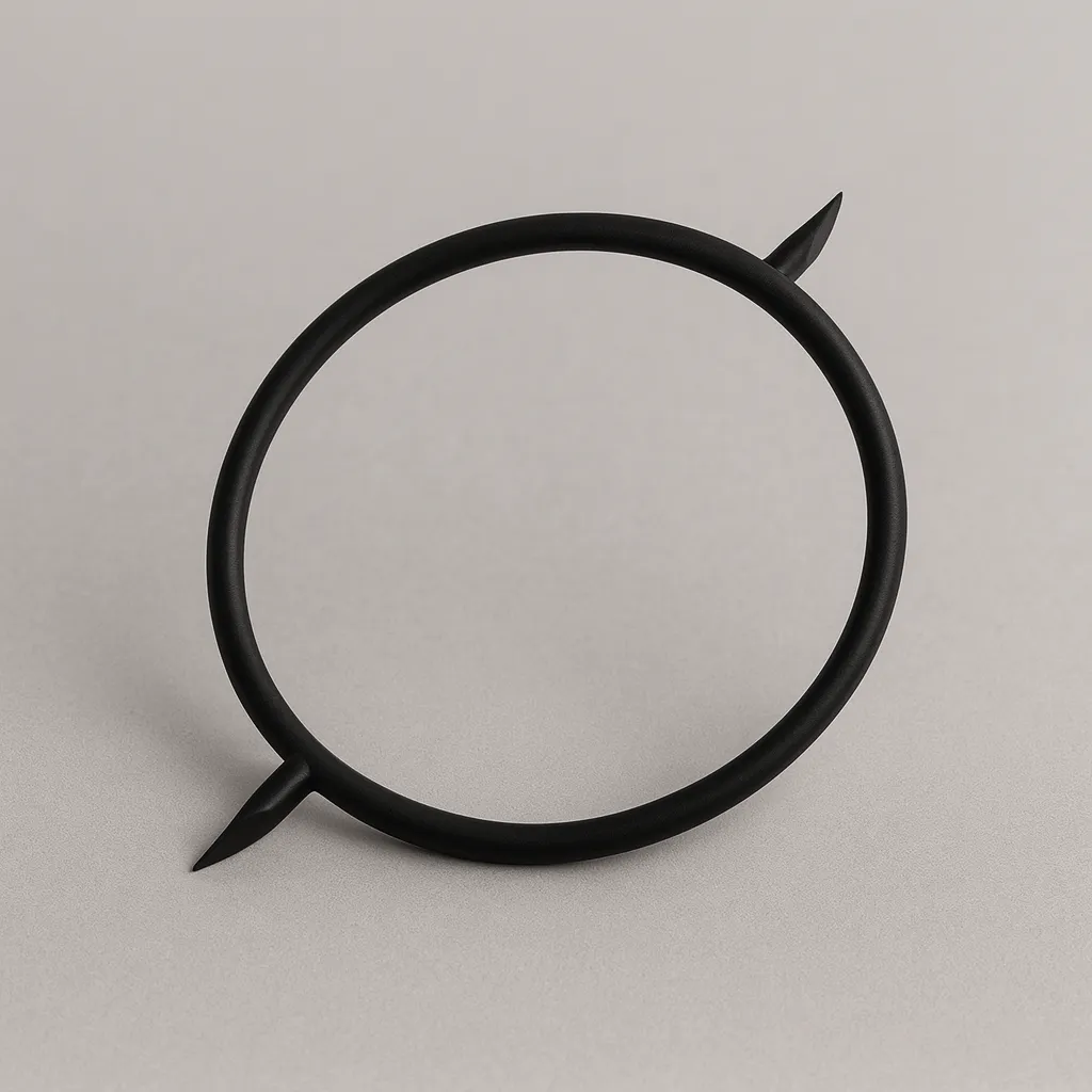
Serie 20 – Silicona peróxido de alto desgarro y alta resistencia térmica (270°C)
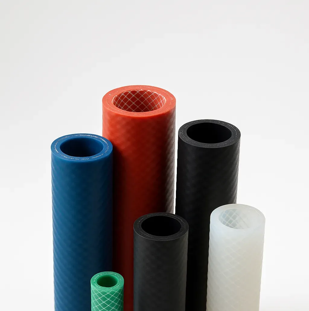
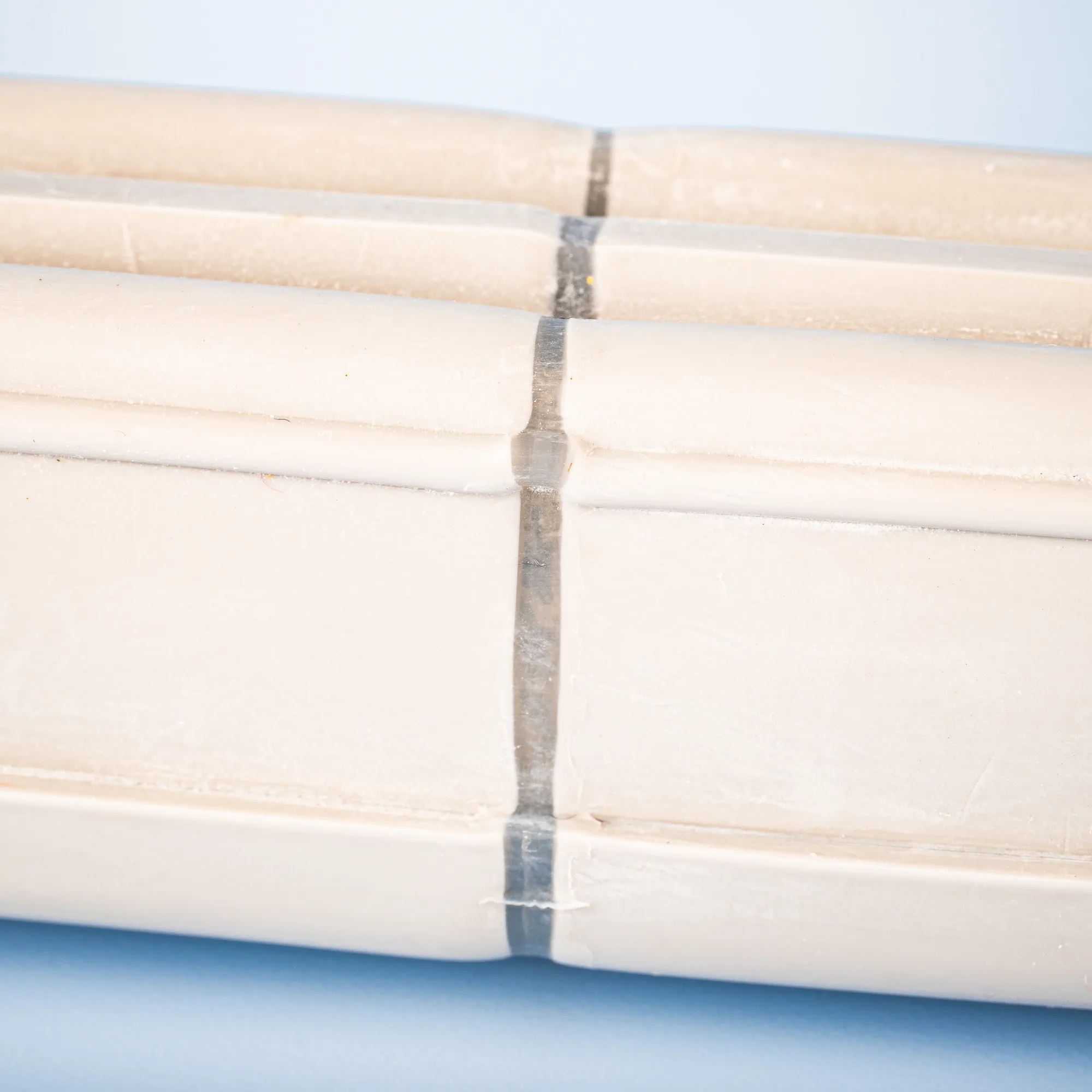
La Serie 20 es una mezcla de silicona catalizada por peróxido que combina dos propiedades críticas: una excelente resistencia al desgarro y una elevada estabilidad térmica. Es transformable por extrusión y moldeo. Esta formulación dual la hace perfecta para aplicaciones que requieren tanto durabilidad mecánica como resistencia a altas temperaturas (hasta +270°C), como juntas hinchables en hornos o perfiles sometidos a tensión en ambientes calientes.
Dureza Shore A45 – 70
Rango de temperatura-60 °C / 270 °C
Densidad (g/cm³)1.12 – 1.20
Resistencia a la tracción (MPa)7.0 – 8.0
Alargamiento a la rotura (%)400 – 550
Resistencia al desgarro (kN/m)30.0 – 36.0
Tipo de catálisisPeróxido
Proceso de transformaciónExtrusión y Moldeo
Color baseNatural / Transparente
Aplicaciones
- Juntas hinchables, perfiles, piezas moldeadas de alta temperatura.
Certificaciones y normas técnicas
- FDA 21 CFR §177.2600
- RoHS compliant
- REACH compliant
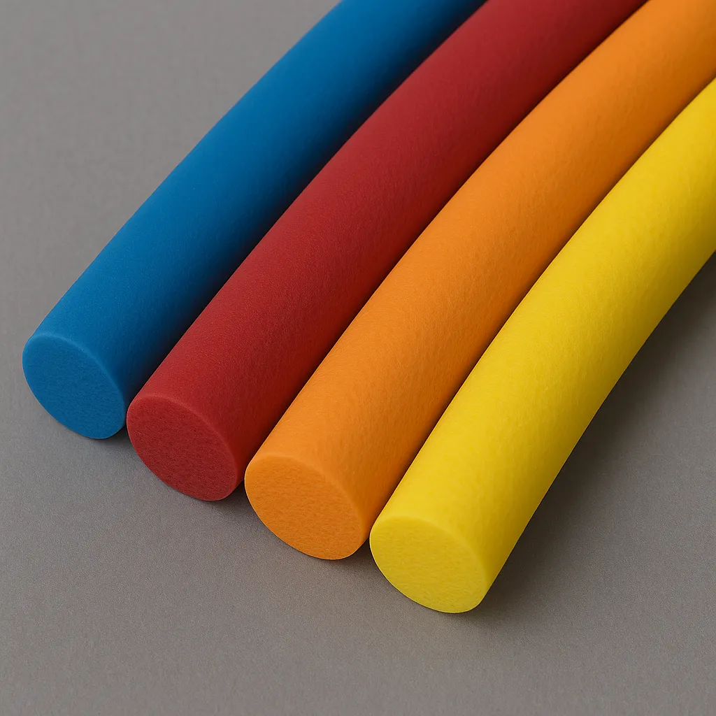
Serie 12 – Silicona platino con buenas propiedades mecánicas y versatilidad
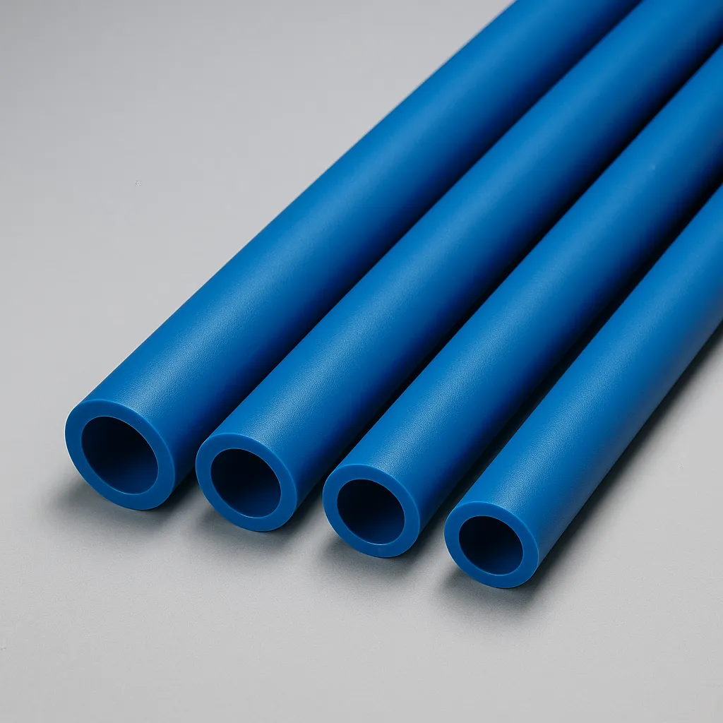
La Serie 12 es una mezcla de silicona catalizada por platino, transformable por extrusión y moldeo, que destaca por sus buenas propiedades mecánicas. Ofrece un rango de durezas muy amplio (de 10 a 90 Shore A) y posibilidad de contacto alimentario. Una característica destacada es que los tubos de aspiración fabricados con la fórmula EQ1260T están validados para integrar dispositivos médicos que requieren marcado CE.
Silicona técnica catalizada por platino con excelentes propiedades mecánicas y amplia disponibilidad de durezas. Transformable por extrusión y moldeo, compatible con contacto alimentario y médico (según formulación).
Dureza Shore A20 – 90
Rango de temperatura-60 °C / 200 °C
Temperatura pico315 °C
Densidad (g/cm³)1.11 – 1.20
Resistencia a la tracción (MPa)6.0 – 9.0
Alargamiento a la rotura (%)100 – 1000
Resistencia al desgarro (kN/m)17.0 – 30.0
Tipo de catálisisPlatino
Proceso de transformaciónExtrusión y Moldeo
Color baseNatural / Transparente
Colores disponiblesColores RAL a petición
Aplicaciones
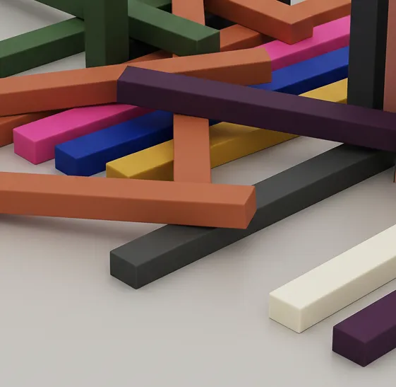
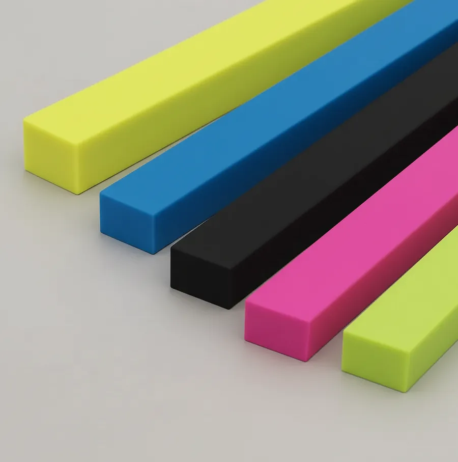
- Tubos (Øint 0.5–145 mm), perfiles (cordones, cuadrados, rectángulos), piezas moldeadas y aplicaciones industriales o médicas.
Certificaciones y normas técnicas
- FDA 21 CFR §177.2600
- BfR IX et XV
- CE 1935/2004
- ISO 10993 (según formulación)
- USP Class VI
- RoHS compliant
- REACH compliant
- NF ISO 7619-1
- NF ISO 37
- NF ISO 34-1
- NF ISO 2781
- ISO 3302 (M2/E1/L2)
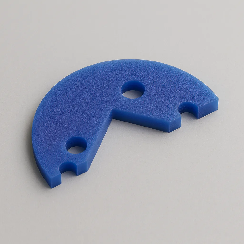
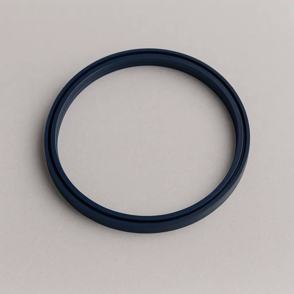
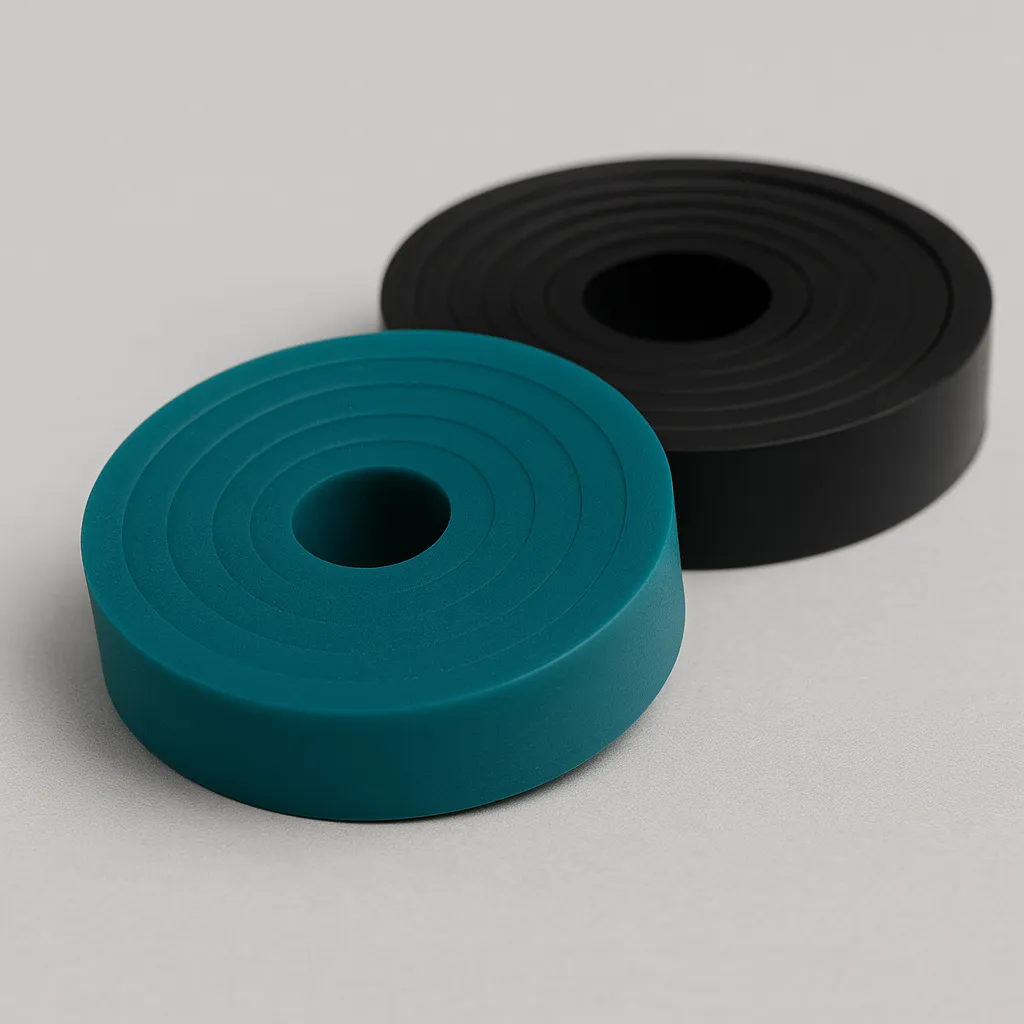
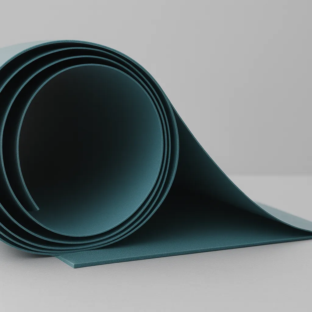
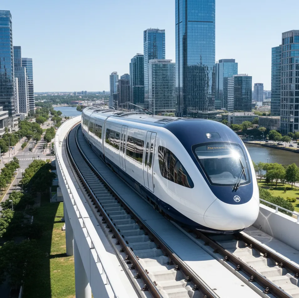
Serie 16 – Silicona peróxido resistente al fuego y autoextinguible (Norma EN 45545-2)
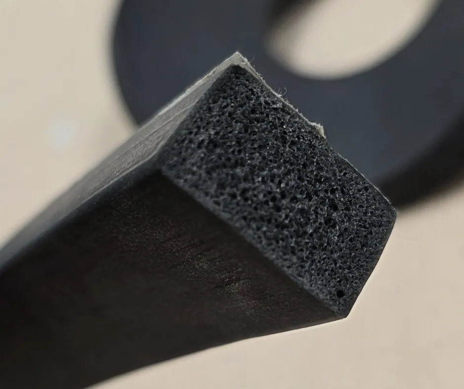
La Serie 16 es una mezcla de silicona catalizada por peróxido, transformable por extrusión y moldeo, diseñada específicamente para ofrecer una excelente resistencia al fuego y propiedades de autoextinguibilidad. Cumple con la normativa ferroviaria EN 45545-2 versión 2020 (Requisitos R22 y R23, niveles HL1, HL2 y HL3), lo que la convierte en la elección ideal para juntas de estanqueidad, perfiles y piezas en entornos donde la seguridad contra incendios es crítica.
Silicona técnica catalizada por peróxido con formulación ignífuga optimizada para el sector ferroviario. Cumple con las exigencias R22/R23 de la norma EN 45545-2:2020 (HL1, HL2, HL3). Transformable por extrusión, ofrece alta resistencia térmica, estabilidad mecánica y baja emisión de humos y gases tóxicos.
Dureza Shore A30 – 85
Rango de temperatura-60 °C / 200 °C
Densidad (g/cm³)1.09 – 1.26
Resistencia a la tracción (MPa)5.0 – 9.0
Alargamiento a la rotura (%)380 – 850
Resistencia al desgarro (kN/m)17.0 – 25.0
Índice de oxígeno (LOI)32.7
Densidad de humos (Ds máx)84.7
ITC / Hazard Level0.06
Nivel de peligro ferroviarioHL1, HL2, HL3
Tipo de catálisisPeróxido
Proceso de transformaciónExtrusión y Moldeo
Color baseNegro / Azul-negro (RAL 9017 / RAL 5004)
Colores disponiblesNegro (RAL 9017), Azul-negro (RAL 5004)
Aplicaciones
- Aplicaciones ferroviarias (juntas, perfiles, sellos, protecciones térmicas, paneles de aislamiento).
Certificaciones y normas técnicas
- EN 45545-2 R22/R23 HL1-HL2-HL3
- RoHS compliant
- REACH compliant
- NF EN 45545-2:2020
- EN ISO 4589-2 (Índice O? 32.7%)
- EN ISO 5659-2 (Ds max 84.7)
- EN 17084 (ITC PNL 0.06)