


A conventional seal works because it is permanently compressed between two surfaces. It functions perfectly well provided those surfaces do not move. The problem arises when a door needs to open, a shaft needs to rotate freely, or a hatch needs to slide — and after that movement, the system must be sealed again. A static seal cannot resolve this: it either prevents movement or permits movement but fails to seal.
The inflatable seal addresses precisely this conflict. At rest, it sits retracted within its groove, making no contact with the opposing surface, and the moving element travels freely. Upon injecting an inflation medium — compressed air, nitrogen, water or other inert gas — the seal expands against the opposing surface, creates a hermetic closure and locks the element in position. When pressure is released, the seal retracts and movement becomes possible once more. It is a binary system, compatible with automation and capable of intermediate pressure states for graduated control.
This article covers the technical criteria for correctly selecting an inflatable silicone seal: which questions to answer before choosing a profile, how expansion mechanics work, what distinguishes each profile family and which specification errors occur most frequently.
Before selecting a profile: define the problem
The temptation is to go directly to reference tables and search for a dimension that fits the available groove. This is a common error. Before selecting a profile, five questions must be answered that determine the entire selection process.
What is the actual gap between surfaces? The distance between the seal mounted in its groove and the surface against which it must seal. This datum determines the minimum expansion required and rules out entire profile families. A 2 mm gap is resolved with a high-pressure HP profile; a 15 mm gap requires a VV or TGD. If the gap is variable (because assembly tolerances are wide or thermal deformation occurs), design for the maximum gap.
What sealing pressure do you require? Sealing against atmospheric pressure is not the same as containing vacuum or internal overpressure. The required sealing pressure determines whether a high-pressure profile (HP, up to 3 bar service) is needed or whether a low-pressure profile (TGD, operating in the millibar range) suffices. Confusing profile service pressure with system containment pressure is a common error.
In which direction must the seal expand? Expansion direction depends on assembly geometry. If the sealing surface is frontal (parallel to the groove base), expansion is axial. If the seal is mounted on an internal diameter and seals against an external cylindrical surface, expansion is radially outward. If it seals against an internal shaft or tube, expansion is radially inward. Each expansion direction has its own minimum bend radii that limit the minimum seal diameter.
What is the operating environment? Temperature, chemical medium in contact, frequency of inflation/deflation cycles, presence of aggressive cleaning agents. Standard silicones for inflatable seals operate between –60 and +200 °C. Food contact requires FDA or EC 1935/2004 formulation. Rail rolling stock requires EN 45545-2. Medical devices require USP Class VI or ISO 10993.
How will the seal be fixed in the groove? Adhesive bonding or mechanical mounting. Adhesive bonding is the standard option when the seal is fitted once and not removed. Mechanical mounting (via valves, gripsters or other fixing elements) is preferable when periodic removal for maintenance is required or when the substrate does not accept adhesive.
With these five answers, profile selection ceases to be a blind search through dimension tables.
How expansion mechanics work
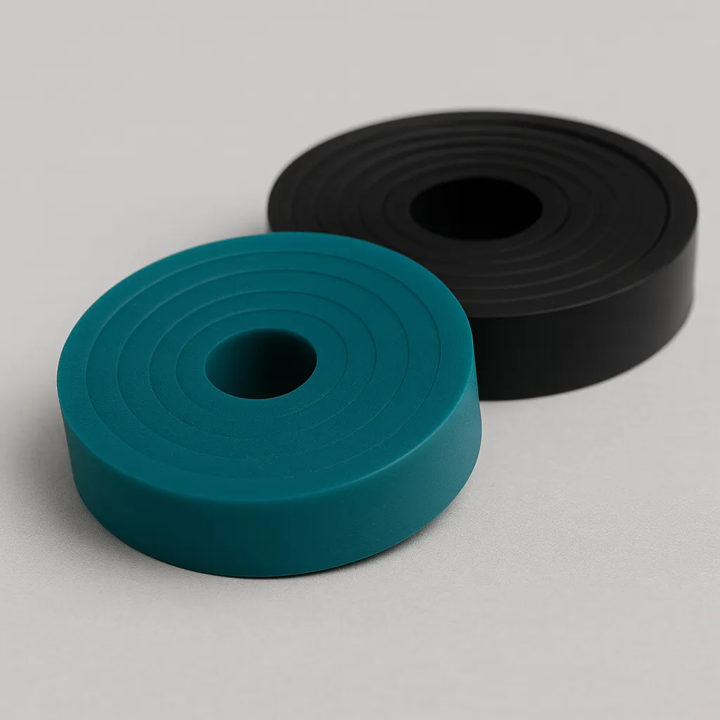
An inflatable seal profile is a tube of designed cross-section that, when internally pressurised, deforms its walls by expanding in a controlled direction. The section geometry — wall thicknesses, bend radii, flexion zones — determines where expansion occurs and how much force is generated against the sealing surface.
There is a concept worth clarifying because it generates confusion: profile service pressure is not the pressure the seal contains, but the pressure injected into the seal itself to make it expand. An HP profile operating at 3 bar service requires 3 bar of compressed air to be injected to achieve its nominal expansion. What that seal can subsequently contain (differential pressure, vacuum, immersion) depends on the resulting contact force and assembly geometry.
Expansion is not linear with pressure. The first few tenths of a bar barely deform the profile; beyond a certain threshold, expansion accelerates until contact is made with the opposing surface; from that point, increasing pressure raises sealing force but barely increases expansion. Exceeding maximum service pressure does not produce better sealing — it produces premature profile fatigue and risk of rupture.
The three expansion directions
| Axial (E.A.) | Radial outward (E.R.E.) | Radial inward (E.R.I.) | |
|---|---|---|---|
| Direction | Perpendicular to mounting plane | Away from axis of curvature | Toward axis of curvature |
| Sealing surface | Frontal, parallel to groove base | External cylindrical | Internal cylindrical (shaft, tube) |
| Minimum radius | R1 (most permissive) | R3 | R2 |
| Typical application | Doors, lids, flat hatches | Seals in cylindrical housings | Sealing against shafts or tubes |
Minimum bend radius is a critical datum frequently overlooked. Each profile has three minimum radii — one for each expansion direction — and they differ from one another. Attempting to bend a profile below its minimum radius causes folds on the inner curve, irregular contact and sealing failure. In small-diameter circular applications, minimum radius may be the factor that rules out an otherwise suitable profile.
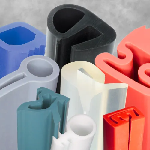
The four profile families
Each family addresses a different combination of service pressure and expansion capability. They are not interchangeable.
HP (High Pressure, Small Development). Compact profiles with sections from 6.3×5 mm to 26×19 mm. Service pressure from 1 to 3 bar depending on reference. Maximum expansion from 1 to 5 mm. This is the profile for small gaps where high sealing force is required: precision hermetic closures, equipment with tight tolerances, seals that must contain significant differential pressure. The reduced section permits integration into compact grooves without compromising frame rigidity.
VV (Variable Volume). Sections from 14×10 mm to 34×25 mm. Service pressure from 1 to 1.5 bar. Expansion from 7 to 20 mm. The profile for large or variable gaps. Variable volume geometry means the internal chamber has a material reserve that deploys progressively upon inflation, permitting coverage of distances the HP cannot reach. Ideal when assembly tolerances are wide or when thermal deformation changes the gap during operation.
TGD (Low Pressure, Very Large Development). Sections from 16×14 mm to 34×28 mm. Service pressure from 1.5 to 5 mbar — note, millibars, not bars. Expansion from 3 to 20 mm. The profile for very large gaps with low sealing pressure. Used in sealed chamber doors, large hatches and perimeter seals for large equipment where sealing is achieved by contact, not by force.
BP (Low Pressure, Large Section). The largest sections in the range: up to 60×35.5 mm. Service pressure of 1.5 bar. Expansion from 8 to 15 mm. Designed for mechanical mounting (not adhesive) with fixing via valves or gripsters. The generous section provides a wide contact surface that compensates for low service pressure.
Quick selection criteria
| Your situation | Recommended profile |
|---|---|
| Small gap (<5 mm), high sealing force required | HP |
| Large or variable gap, moderate sealing force | VV |
| Very large gap, low sealing pressure (mbar) | TGD |
| Large section, mechanical mounting, wide contact surface | BP |
| Gap unknown but variable | VV (most versatile) |
Material: three compounds, one decision
Inflatable silicone seals are manufactured from high tear-strength compounds — between 35 and 40 kN/m — because each inflation/deflation cycle subjects the profile walls to repeated flexion. A standard silicone with 10–15 kN/m tear strength would crack within a few hundred cycles.
Compound selection reduces to choosing hardness: 50, 60 or 70 Shore A.
50 Shore A provides maximum flexibility. The seal inflates at lower pressure, adapts better to irregular surfaces and exerts less force on delicate substrates. This is the option when available inflation force is limited or when the sealing surface is not perfectly smooth.
60 Shore A is the default balance. Sufficient flexibility for comfortable inflation with good dimensional stability and mechanical resistance. If there is no technical reason to choose another hardness, this is the choice.
70 Shore A provides greater rigidity and resistance to internal pressure. For applications with high service pressures or where the seal must maintain its shape precisely even at rest. Trade-off: requires more inflation pressure to achieve the same expansion.
A consideration rarely found in catalogues: hardness directly affects system response speed. A 50 Shore A profile expands faster at the same pressure than a 70 Shore A profile. In automated systems where closing time is critical, hardness enters the cycle time equation.
For applications with specific regulatory requirements — food contact, medical devices, rail rolling stock — certified formulations are available that apply to the same profiles in the range. The geometry does not change; the compound changes.
Anatomy of the complete system
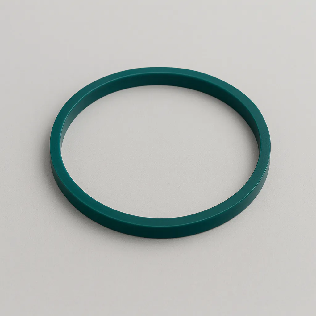
An inflatable silicone seal is not merely the profile. It is a system comprising four components that must be specified together.
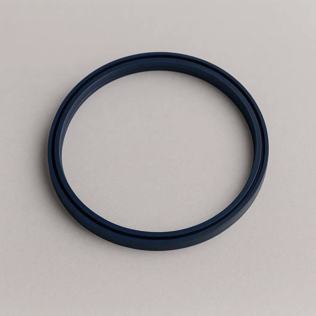
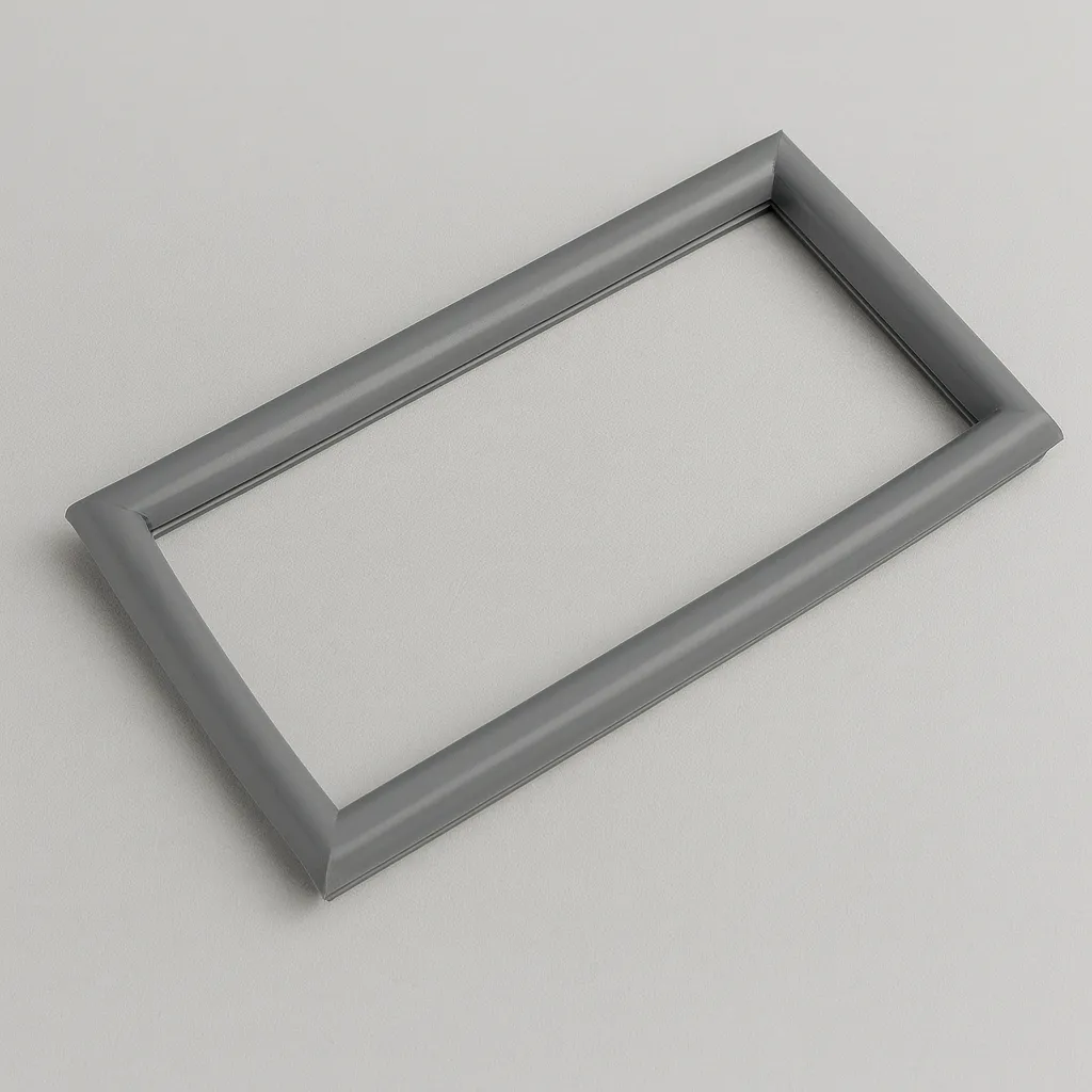
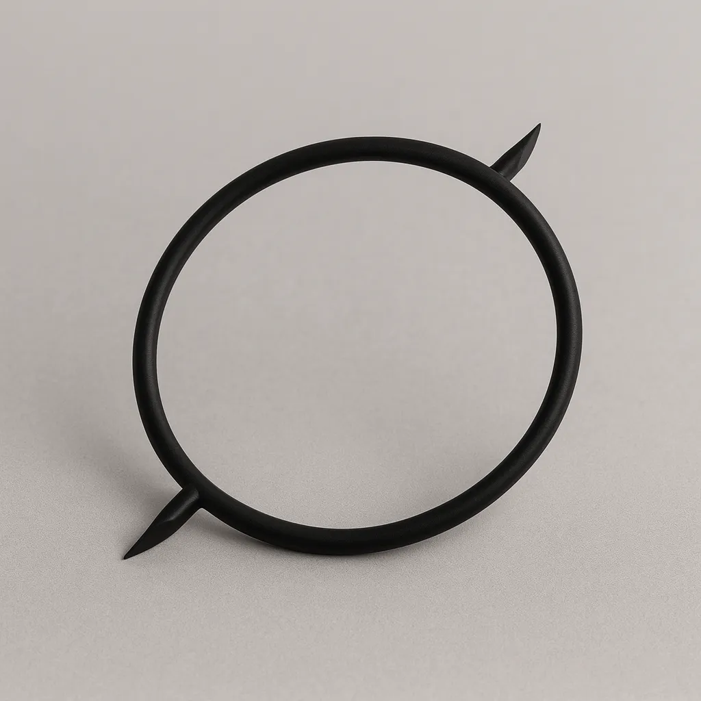
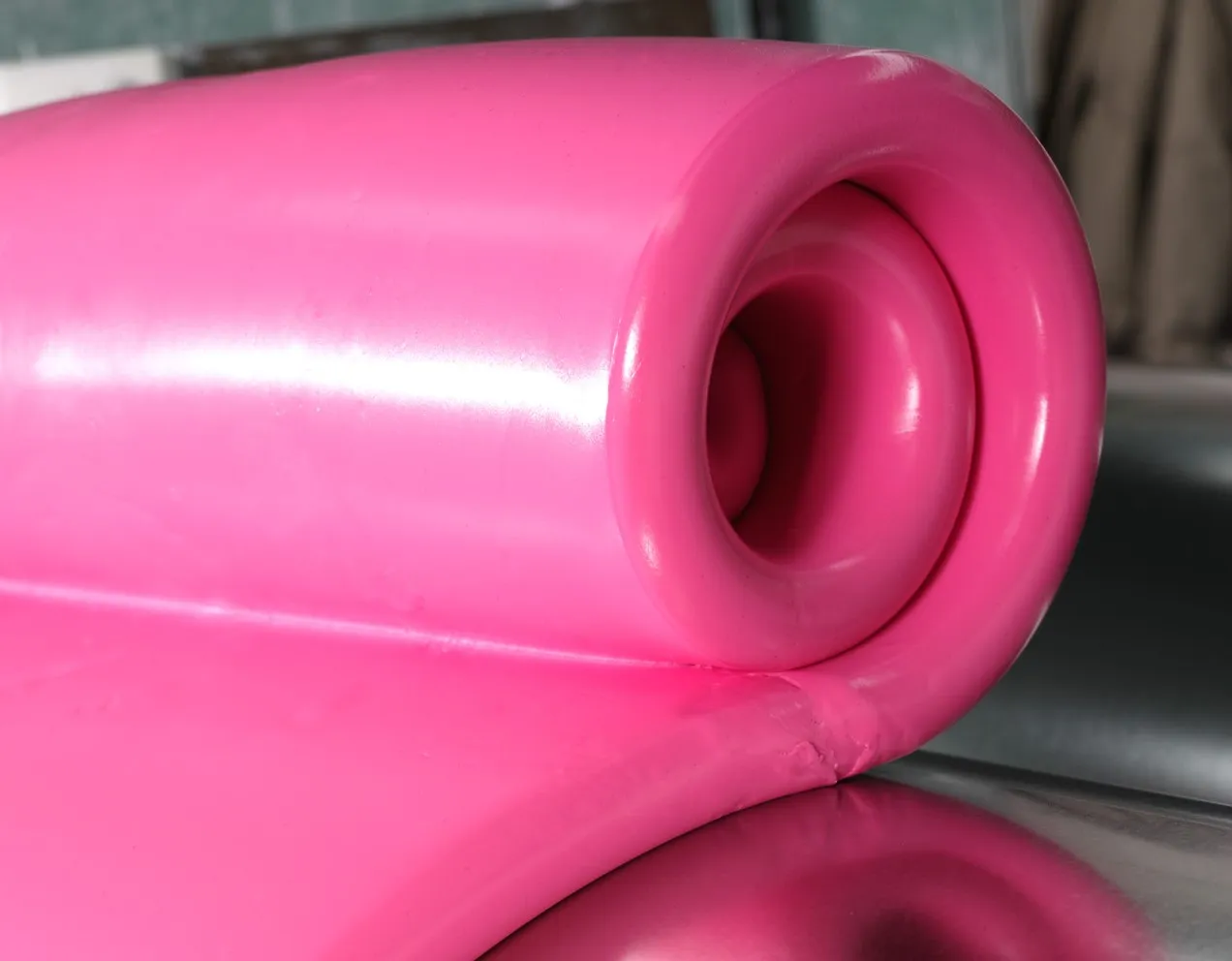
The profile is the seal body, manufactured by extrusion and closed upon itself by welding to form a ring (in circular or oval configurations) or with end plugs (in linear configurations). The weld is a critical point: it is performed using a specific technique that avoids stress concentration at the interface so as not to compromise fatigue life.
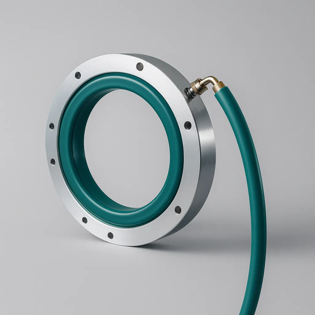
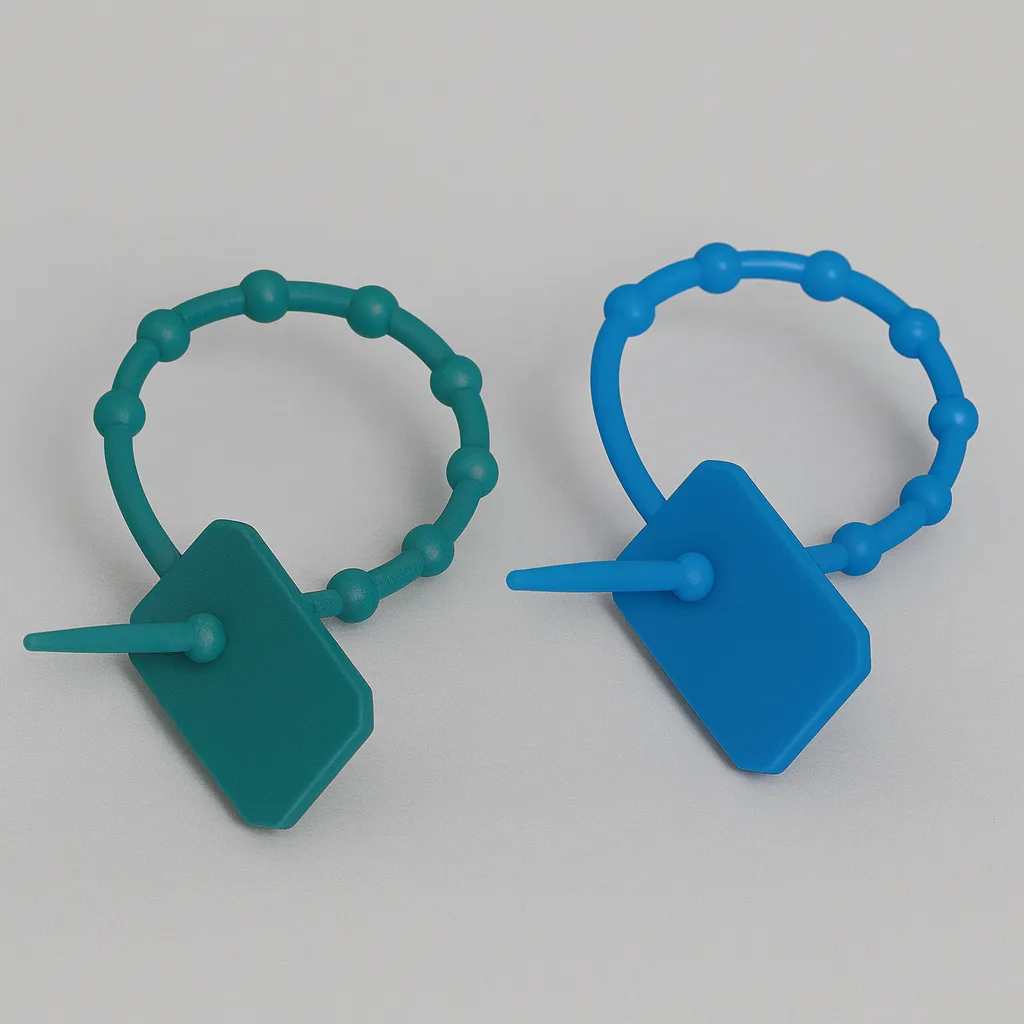
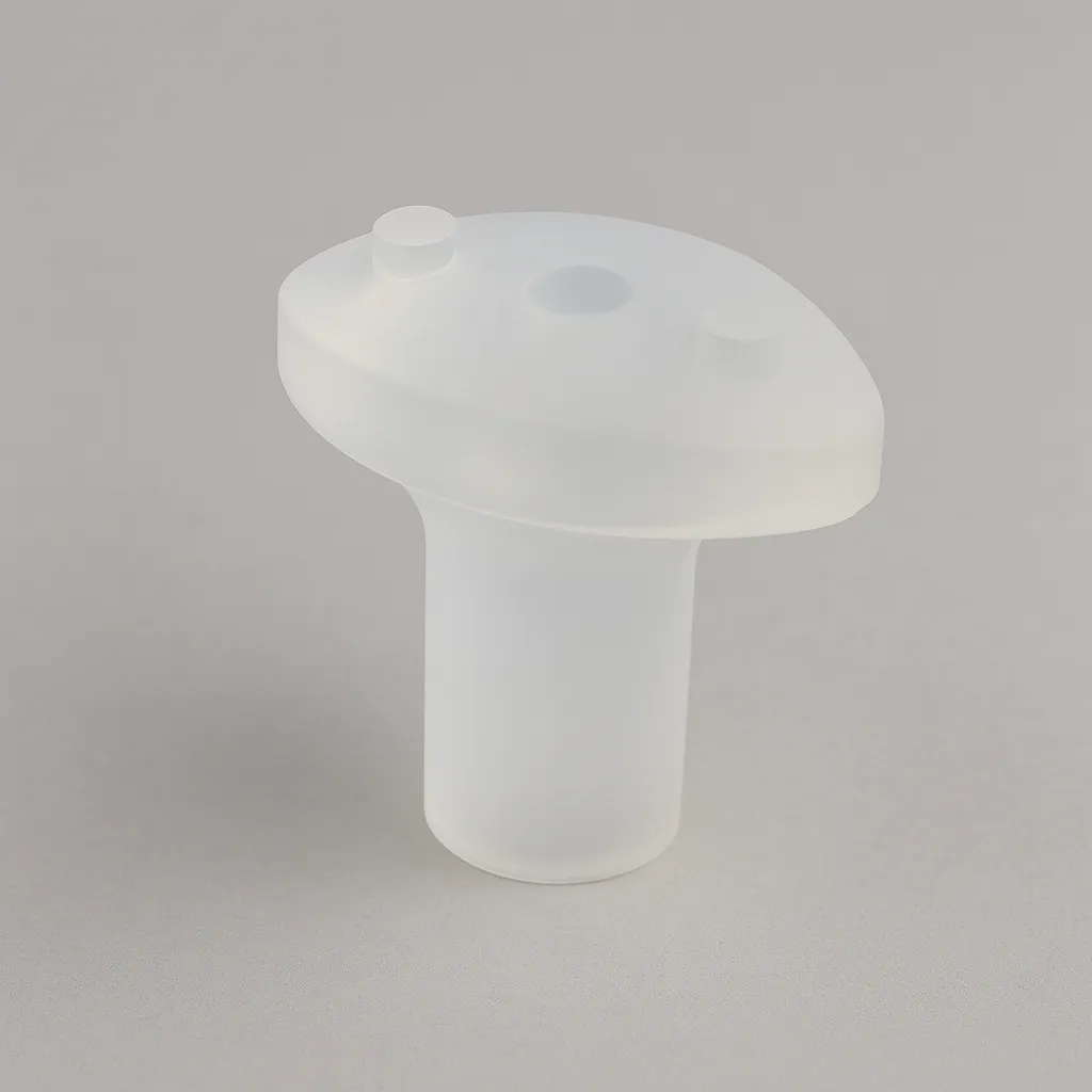
The overmoulded cone is the component connecting the valve to the profile interior. It is manufactured directly onto the seal during assembly, creating a hermetic joint without weak points. Its geometry depends on valve diameter and space available in the groove — verify that the cone does not protrude from the groove or interfere with the moving element.
The inflation valve is the connection between the pneumatic system and seal interior. In stainless steel or brass, with different thread configurations and lengths according to mounting space. An important detail: do not overtighten the valve onto the cone. Silicone overmoulding has a torque limit; exceeding it damages the cone and causes leaks that can be difficult to diagnose.
And the fixing system: adhesive or mechanical. Adhesive bonding requires prior cleaning with alcohol, primer application if the substrate requires it, and 12–24 hours drying before operation. This is time that must be planned into the assembly sequence. Mechanical mounting avoids that waiting time but requires the frame to be designed with housings for fixing elements.
Groove design
The groove is the other half of the equation and its design is frequently underestimated. A well-selected profile mounted in a poorly dimensioned groove will perform badly or simply not work.
Groove dimensions (L1 × H1 in manufacturer tables) are slightly larger than profile section (L × H). This clearance is intentional: it permits housing the profile without compression at rest, guarantees space for elastic return after deflation and facilitates assembly. Manufacturing the groove exactly to profile dimensions — « so it fits snugly » — is an error that prevents complete retraction and accelerates fatigue.
The groove base must be smooth and free of burrs. Entry edges must be radiused or at minimum deburred. A sharp edge in the zone where the profile flexes during inflation acts as a stress concentrator and is the initiation point for cracks.
For the inflation valve, a through-hole in the groove base or side is required, dimensioned according to the chosen cone reference. The position of this hole determines where the pneumatic connection goes, which must be considered from frame design stage.
Common specification errors
Four errors recur repeatedly and can be avoided with correct specification from the outset.
The first is confusing profile service pressure with system pressure. Service pressure is what is injected into the seal to inflate it. It is not the differential pressure the seal can contain once inflated. Specifying an HP profile with 3 bar service thinking it will contain 3 bar differential pressure is a conceptual error leading to in-service failures.
The second is not verifying minimum bend radius. Each profile has three different minimum radii — one for each expansion direction. In small-diameter circular applications, minimum radius may force a change of profile family even though expansion and pressure are correct. This is a datum that must always be checked, especially for radial expansion.
The third is inflating the seal outside the groove. It seems obvious but it happens: during leak tests prior to assembly, during incoming inspection or simply out of curiosity. Without groove confinement, the profile expands in all directions without control, deforms permanently and is rendered unusable. First pressurisation must always be performed with the seal mounted in its housing.
The fourth is oversizing the groove « for safety ». An oversized groove permits the profile to shift during inflation, loses expansion orientation and contact with the sealing surface becomes irregular. The clearance between profile and groove is calculated by the manufacturer; respecting it is part of the specification.
Need a custom inflatable seal?
If you have the gap, sealing pressure and expansion direction, you have what is needed to begin.
Request technical assessment →