


Every silicone profile that fails in service can be traced back to a decision made before manufacturing began. It is rarely the material. It is rarely the extrusion process. It is almost invariably one of three things: the geometry was unsuitable for the installation conditions, the compound was incompatible with the actual service environment, or the construction type did not match the available closing force.
This article provides the decision framework to avoid those failures. It is not a catalogue. It is the technical rationale behind every custom extruded silicone profile: which questions to answer before committing to any design, how geometry is selected, what determines compound choice, and what each construction type implies.
Before selecting anything: define the service conditions
The common temptation is to begin by selecting a material or shape. This is an error. The first step is to define the environment in which the profile will operate, because those conditions determine everything that follows.
Six variables define the starting point:
The actual temperature range — and by « actual » we mean continuous service temperature, not peak exposure. A profile operating at +180 °C continuously with occasional peaks to +220 °C requires a different formulation from one operating at +220 °C continuously.
The chemical environment — air, steam, water, mineral oil, fuel, foodstuffs, CIP cleaning agents. Each medium rules out entire compound families or makes them mandatory.
The available closing force — how much force can the frame, lid or door exert on the profile. This determines whether solid rubber is suitable or whether cellular or tubular hollow construction is required.
Whether there is relative movement between mating surfaces — static (the seal is fitted and remains compressed) or dynamic (sliding, vibration, frequent opening/closing). Movement dictates geometry and hardness selection.
Assembly and disassembly frequency — a profile installed once and left in place has different mechanical requirements from one removed for maintenance every week.
Applicable regulatory requirements — FDA for food contact in the US, EC 1935/2004 for Europe, USP Class VI or ISO 10993 for medical devices, EN 45545-2 for rail rolling stock. Not all formulations comply with all standards, and not all levels of requirement within a given standard are achievable with every compound.
Geometry: cross-section determines mechanical behaviour
Profile shape is not aesthetic. Each geometry responds differently under compression, requires a different closing force and is fitted in a different manner. Selecting the correct cross-section is the first critical technical decision.
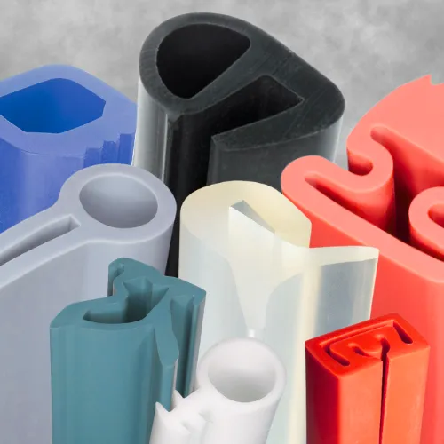
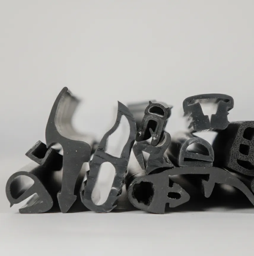
D-section profile
Hollow semi-circular section with flat mounting base. The hollow chamber deforms to absorb impact with minimal closing force. The flat base is adhesive-bonded or mechanically fixed to the substrate. This is the reference geometry where sealing with shock absorption is required: doors closing against frames, hinged covers, hatches with pressure closure. Minimum wall thickness is 1 mm in solid rubber and 1.5 mm in cellular.
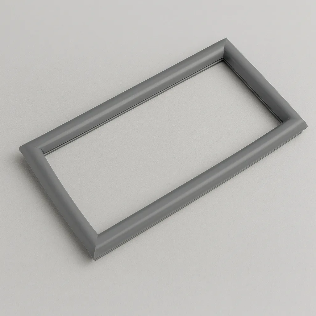
P-section profile (bulb seal)
Bulb with anchor foot that inserts into a channel in the frame. The bulb provides compressibility and contact surface; the foot holds it in position. This is the standard seal in structural glazing, rail and road vehicle doors, and panel sealing with mounting channels. Recommended compression is 15–25% of bulb diameter.
U-section profile
Open channel that clips onto the edge of sheet metal or panel. Protects the edge and may incorporate a lateral sealing lip. Retention depends on material hardness — 50 to 70 Shore A provides the best balance between grip and ease of assembly. Internal metal reinforcement improves retention in vibration environments.
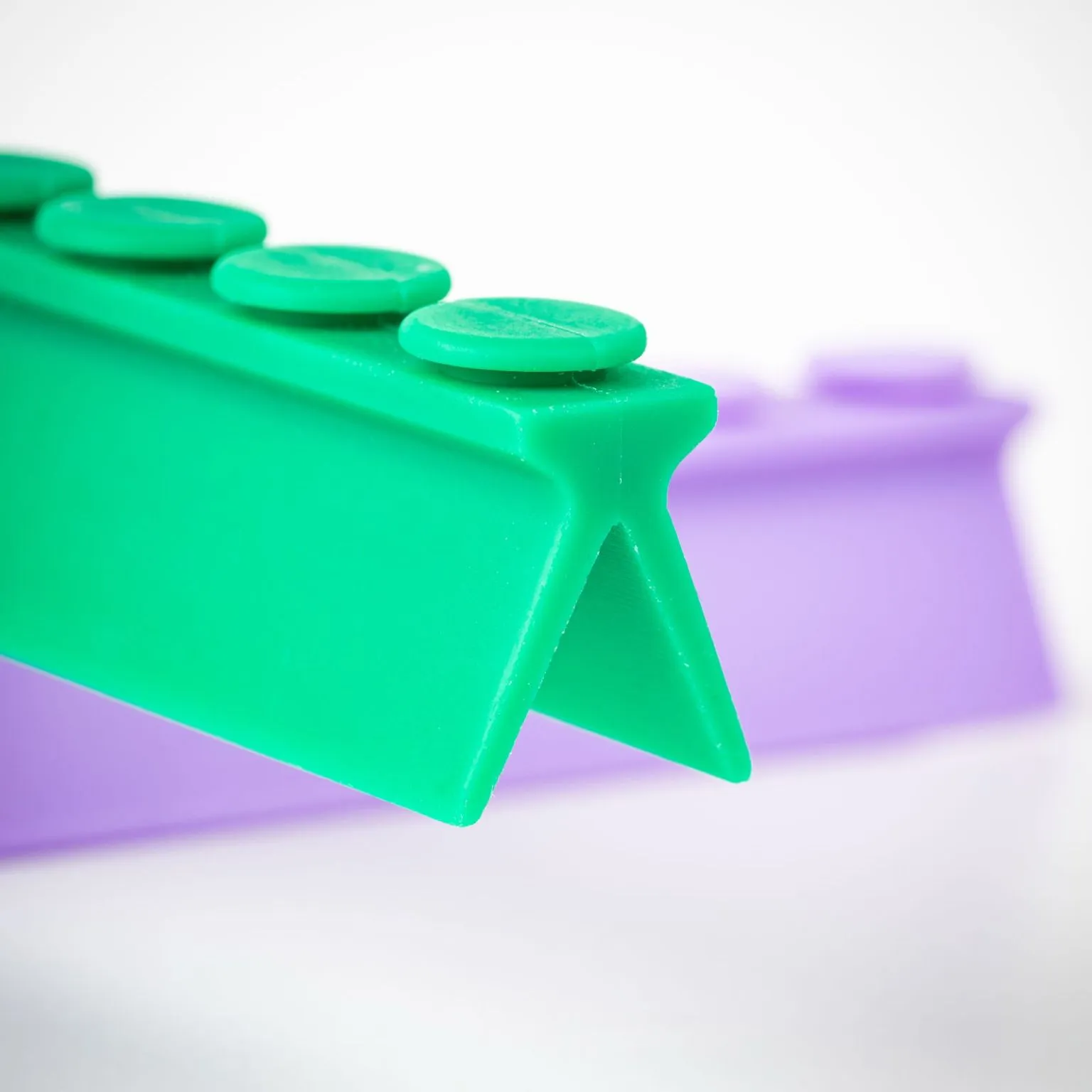
T-section profile
The stem inserts into a channel whilst the upper wings seal against the surface. Highly stable against lateral displacement, making it ideal for expansion joints and sealing between adjacent panels.
E-section profile (double lip)
Combines channel retention with dual sealing points. The two lips create redundancy for safety-critical seals or allow sealing against surfaces at different heights. Minimum lip thickness: 0.8 mm.
Single lip profile
Flexible blade with anchor base. Seals through light contact with very low friction, making it the correct choice where there is relative movement between parts: sliding doors, dynamic seals against shafts, wiper elements.
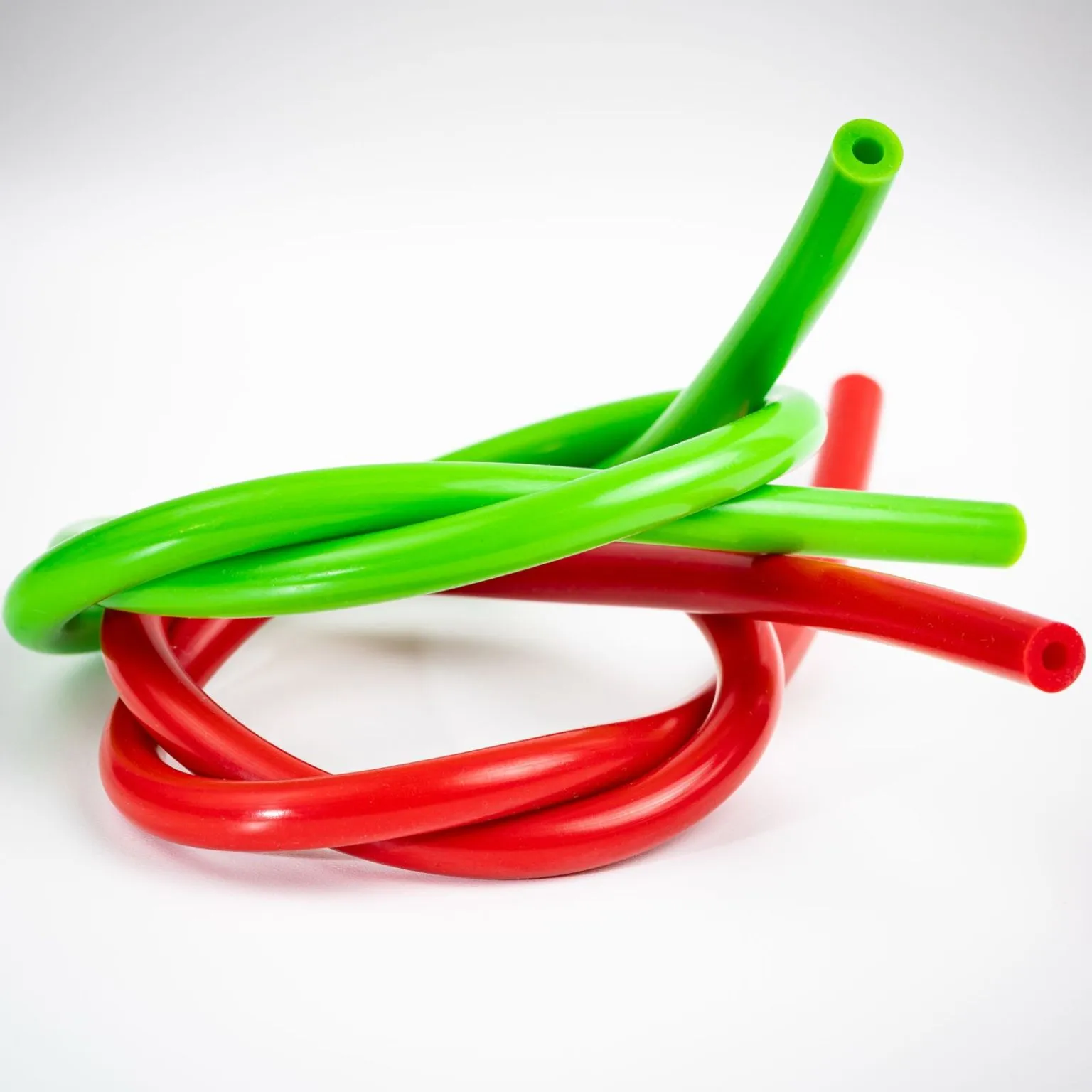
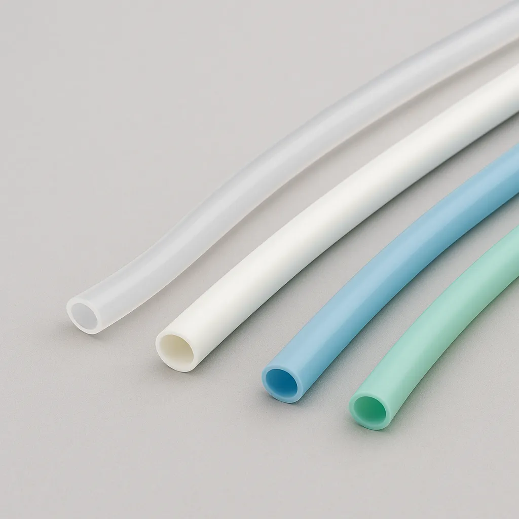
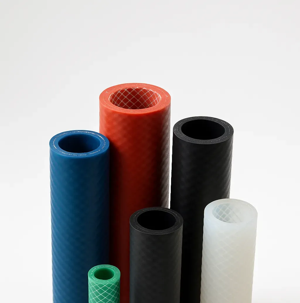
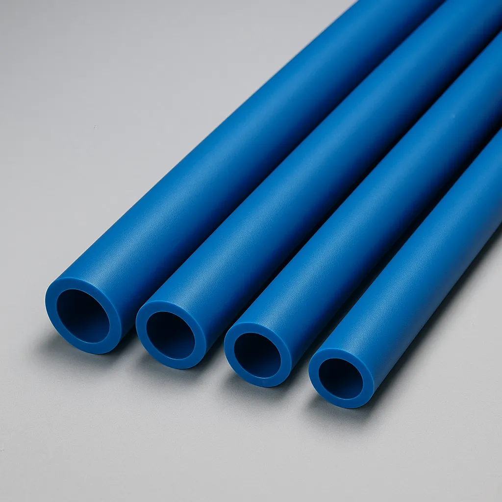
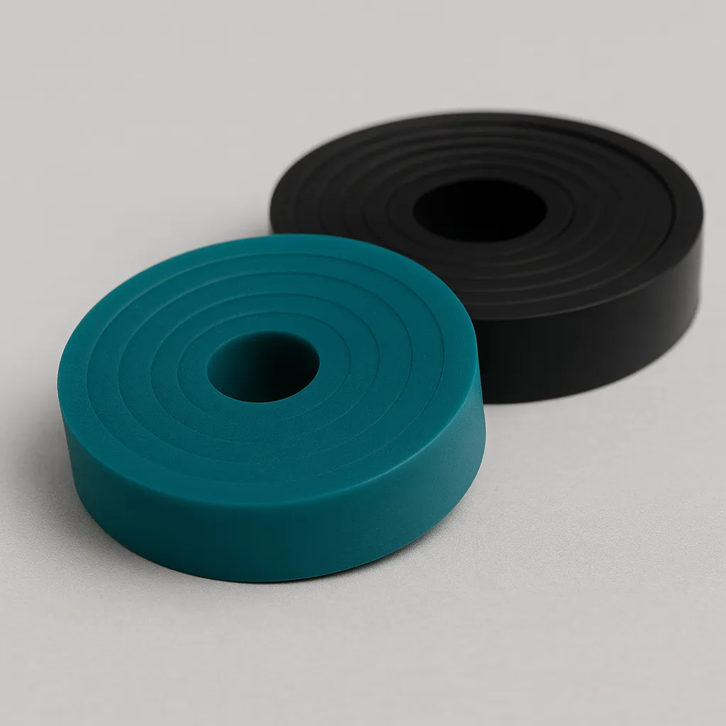
Hollow tubular profile
Closed section with internal cavity. Offers the lowest closing force of all geometries and excellent elastic recovery. Not to be confused with conveying tubing — the function here is sealing, not fluid transport. This is the solution where the substrate is fragile or available closing force is severely limited.
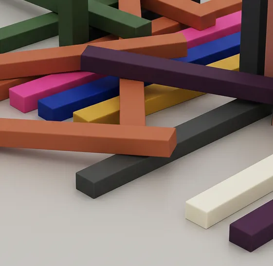
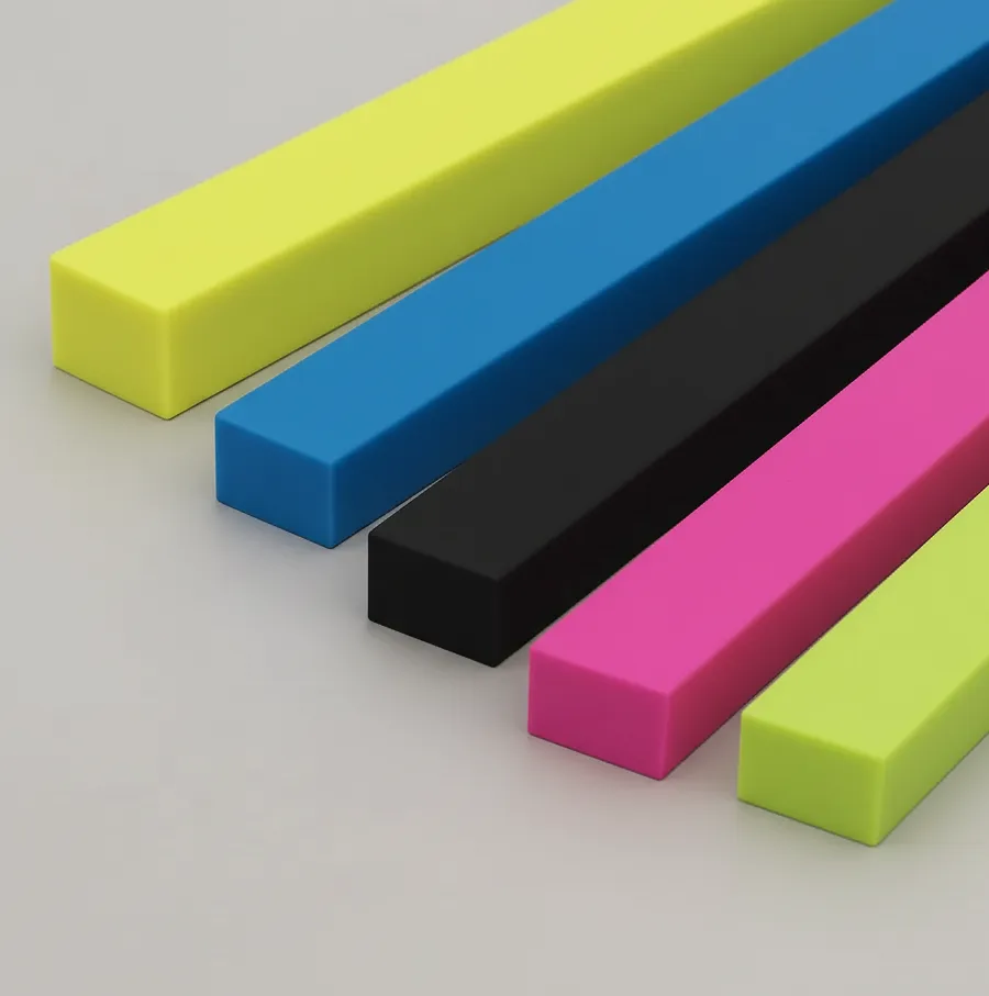
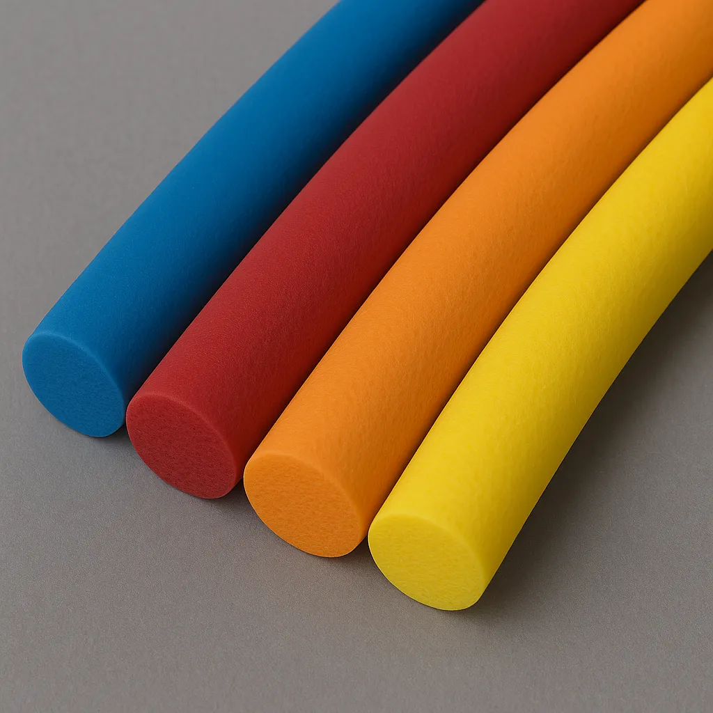
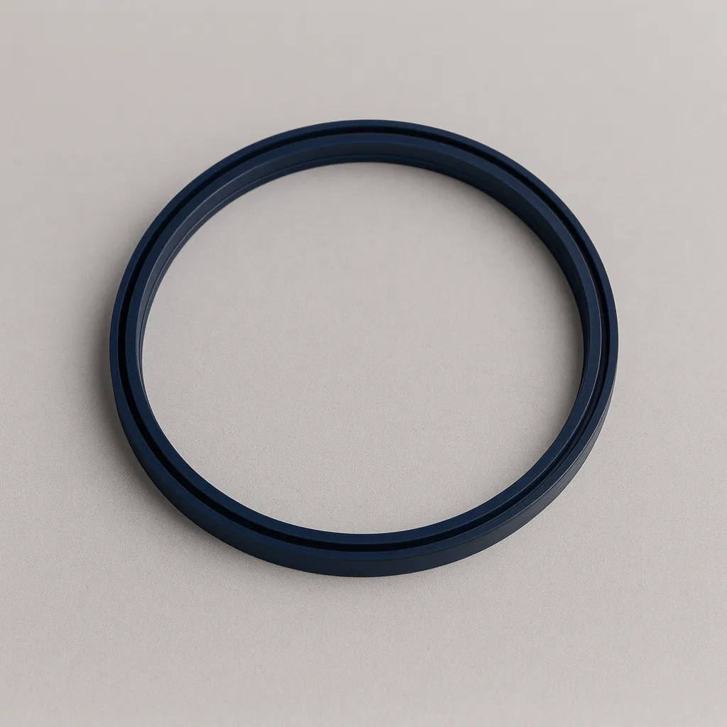
Solid cord
Solid circular section without cavity. Used as stock for fabricating non-standard diameter O-rings (by vulcanising the ends), end stops and channel sealing. Compression in channel between 15 and 30% of diameter.
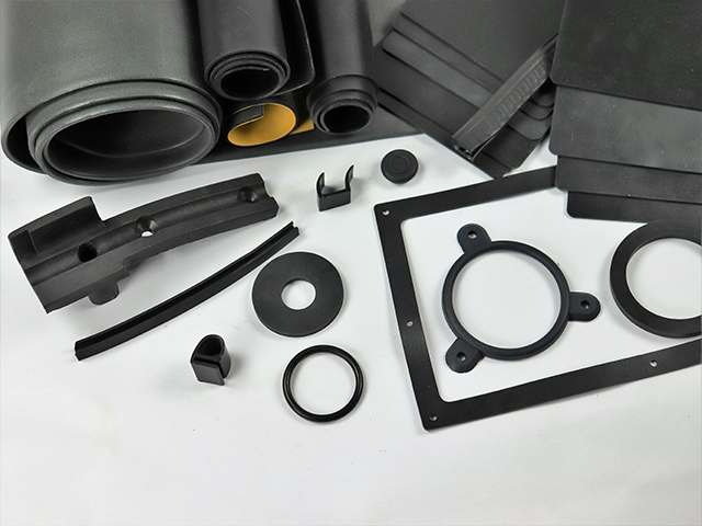
Any of these geometries can be manufactured in solid, cellular or co-extruded form, and combined with inserts. Geometry and construction type are selected together because they are mutually dependent.
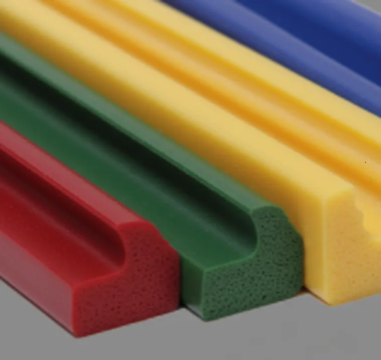
Construction type: solid, cellular, co-extruded or with insert
The second decision is how the profile is constructed internally. Four options, each with its implications:
| Solid (compact) | Cellular (sponge) | Co-extruded | With insert | |
|---|---|---|---|---|
| Structure | Homogeneous, single compound | Closed-cell expanded | 2+ materials simultaneously | Embedded metal/textile core |
| Density | 1.07–1.46 g/cm³ | 0.5–0.8 g/cm³ | Per combination | Per insert type |
| Closing force | Medium to high | Very low | Variable by zone | Medium to high |
| Tolerances (ISO 3302-1) | E1, E2 | E3 (wider) | E1/E2 for solid zones | E1/E2 |
| When to specify | Default choice | Fragile substrates, low force available | Different properties by zone | Tensile strength, stiffness, vibration |
Solid is the default choice unless there is a technical reason to specify otherwise. It offers the best mechanical properties, the widest range of available formulations and the lowest cost.
Cellular makes sense when available closing force is limited or the substrate cannot tolerate pressure. Compressibility is far superior to solid, but mechanical properties are lower and dimensional tolerances wider. Two principal families: standard cellular with FDA/EC 1935/2004 food certification, and flame-retardant cellular with EN 45545-2 certification for rail applications.
Co-extruded is justified when the application genuinely requires different properties in different zones of the same part. The most common example is a 70 Shore A base for mechanical anchoring with a 40 Shore A lip for soft sealing. It also permits combining a solid core with cellular exterior, or integrating a conductive silicone zone in an otherwise insulating profile. Adds complexity to tooling and process.
With insert addresses situations where the profile requires longitudinal tensile strength, stiffness that silicone alone cannot provide, or clip-on mounting to metal edges. Common inserts include stainless steel mesh, textile tape, metal strip and reinforcing wire.
Material: compound selection determines service life
Geometry defines how the profile seals; the material defines how long it lasts and under what conditions it can operate. Silicone is not a single material — there are compound families with radically different properties.
Temperature range as first filter. Standard VMQ silicones operate between –60 and +200 °C. Above +200 °C, high-temperature formulations are required, achieving +270 °C or +300 °C continuous depending on compound. Below –60 °C, phenyl silicone (PVMQ) is required, maintaining flexibility to –110 °C due to the phenyl groups preventing polymer crystallisation.
Chemical exposure as second filter. Standard silicone has good resistance to water, steam, oxygen, ozone and most inorganic chemicals. However, it swells and degrades on contact with hydrocarbons, mineral oils and organic solvents. For such environments, fluorosilicone (FVMQ) is required, incorporating trifluoropropyl groups that provide substantially superior chemical resistance. Note: FVMQ is significantly denser (1.40–1.46 g/cm³ versus 1.10–1.20 g/cm³ for VMQ) and has a narrower temperature range (–60 to +170 °C).
Regulatory requirements as third filter. Food contact requires FDA 21 CFR 177.2600 certification for the US or EC 1935/2004 Regulation for Europe. Medical devices require demonstrated biocompatibility per USP Class VI or ISO 10993. Rail rolling stock requires EN 45545-2 compliance for fire, smoke and toxicity — requirement sets R22 and R23 are most common for seals and gaskets, with hazard levels HL1 to HL3 depending on vehicle operating category. Not all formulations achieve all levels: HL3 is the most demanding and limits material and colour options.
Mechanical properties as fourth filter. If the profile will undergo frequent assembly and disassembly, repeated mechanical stress or has fine geometries (lips, fins), tear strength is critical. High-tear silicones achieve 33–55 kN/m versus 10–23 kN/m for standard — this is the difference between a lip that tears on first removal and one that withstands hundreds of cycles. If the seal will remain permanently compressed (flanges, bolted covers), the determining factor is compression set: formulations are available achieving 11–18% versus the typical 25–40%.
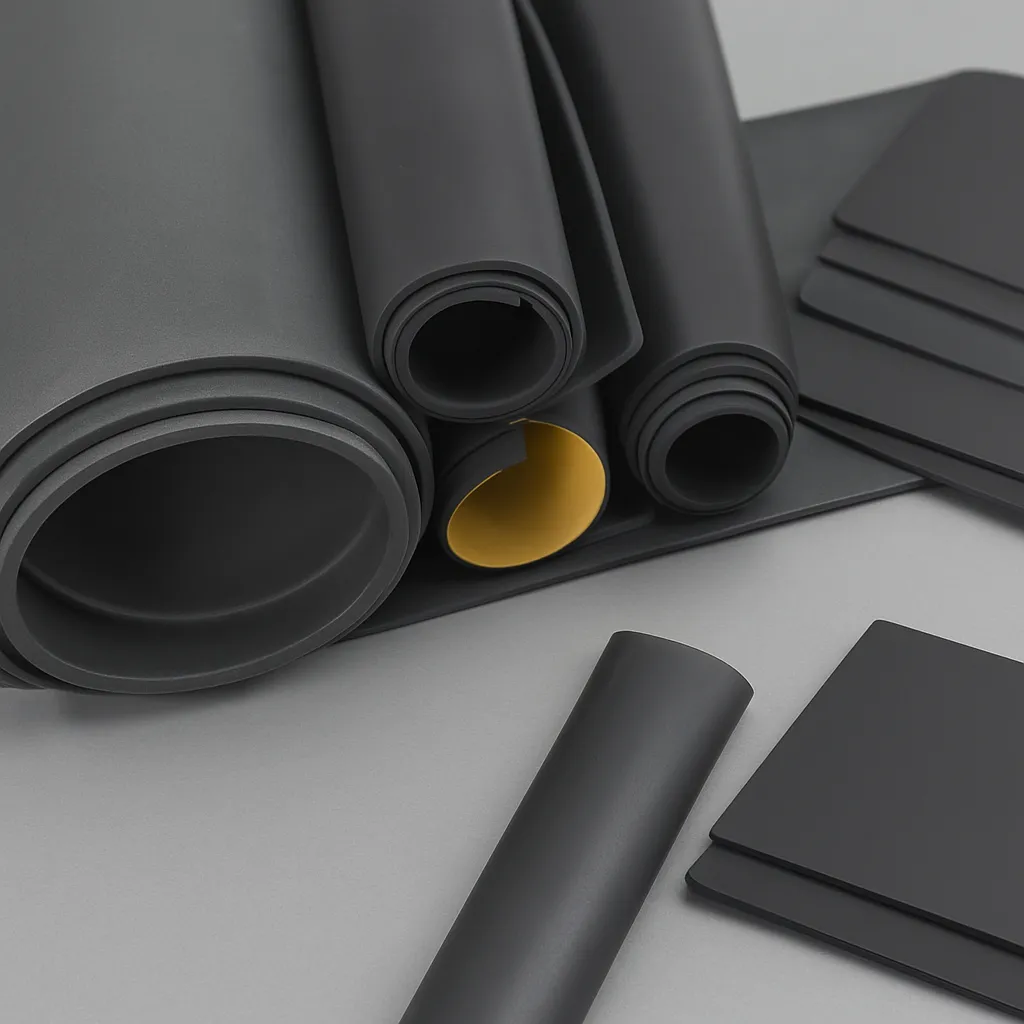
Tolerances and extrusion considerations
Tolerances in silicone extrusion are wider than in injection moulding, and it is important to understand this to avoid unrealistic expectations.
The reference standard is ISO 3302-1. Solid extruded profiles are normally manufactured to class E1 or E2. Cellular profiles work to class E3, with wider tolerances because expanded material density is less controllable than solid. Cut lengths are controlled to class L2.
Silicone shrinks during vulcanisation, and the degree of shrinkage varies with formulation, colour and extrusion speed. The tooling (die) is designed oversized to compensate for this shrinkage, and the first metres of production are devoted to adjusting parameters until the section meets specification. For complex profiles — co-extruded, with insert or with asymmetric geometries — more than one adjustment iteration may be required.
Dark colours tend to be more dimensionally stable than light ones. And formulations with high mineral filler loading have higher densities and different shrinkage behaviour compared to standard silicones.
From drawing to profile: what to expect from the process
Custom silicone profile development proceeds through five phases: specification receipt, compound selection, tooling design and manufacture, extrusion trials with sample submission for validation, and series production with batch certificate.
Lead time for new development with tooling is between 4 and 8 weeks depending on complexity. Repeat orders with existing tooling move between 2 and 4 weeks depending on volume. Manufacturing takes place in an ISO 9001 and ISO 13485 certified environment, with ISO 8 cleanroom available for medical applications.
A perfect CAD drawing is not required to begin. A hand sketch with approximate dimensions and a clear description of service conditions is sufficient to start. What matters is not the quality of the drawing but the quality of the information: actual temperature, chemical environment, available closing force, applicable regulations.
Common specification errors
Three errors appear repeatedly and can be avoided from the initial specification stage.
The first is confusing peak temperature with continuous service temperature. That a silicone can withstand peaks of +315 °C does not mean it can operate at that temperature permanently. The relevant datum for material selection is maximum continuous service temperature, not peak.
The second is specifying hardness without considering geometry. A hollow tubular profile in 70 Shore A may require more closing force than expected because material stiffness adds to the geometric stiffness of the section. The combined effect of hardness and geometry on closing force must be evaluated together.
The third is not considering compression set in permanently compressed seals. A standard silicone with 35% compression set will lose a third of its recovery capacity over time. If the seal operates compressed for months or years, a low compression set formulation (11–18%) significantly extends sealing service life.
Need a custom silicone profile?
Whether you have a drawing, a sample or just the service conditions, that is the correct starting point.
Request technical assessment →