














CAD product design
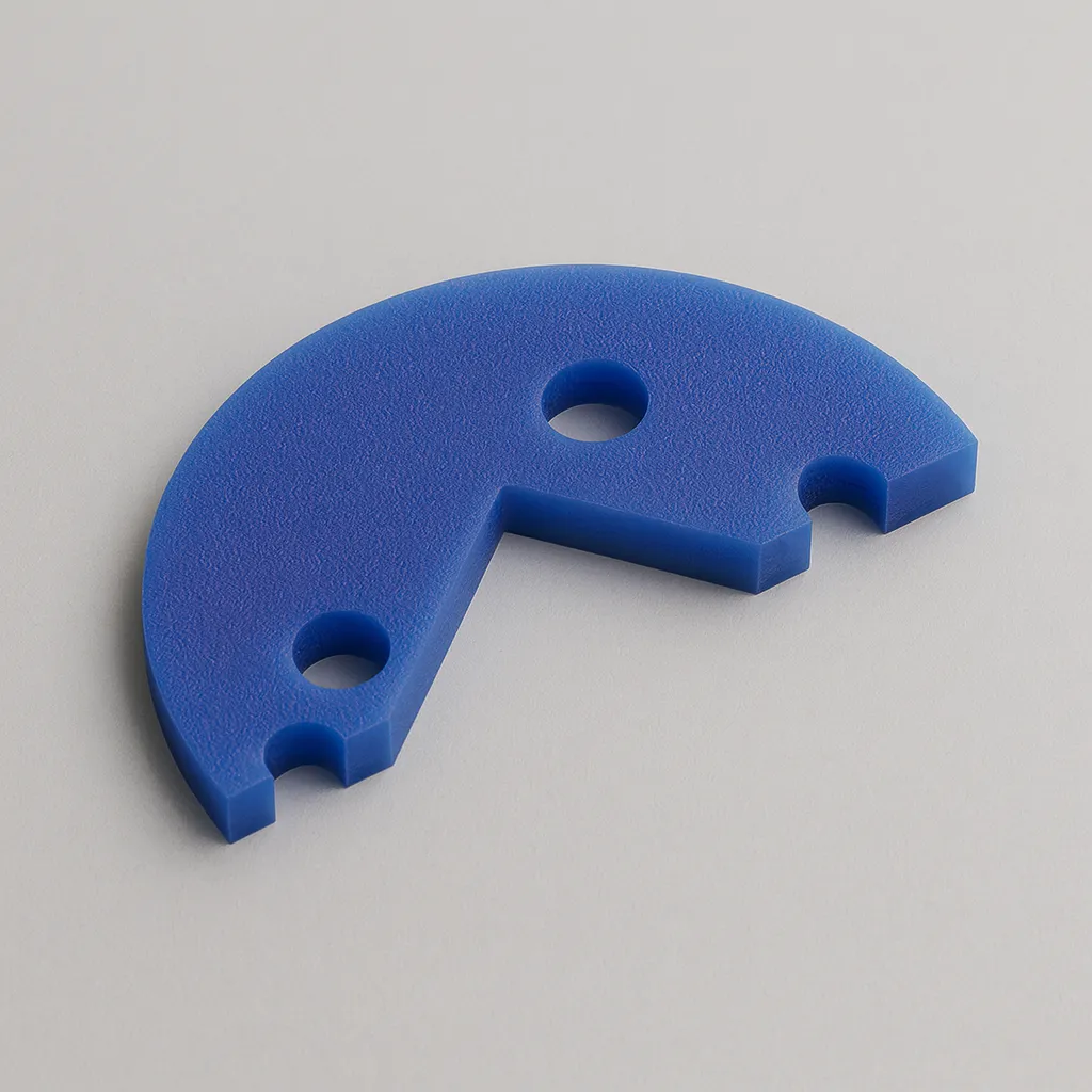
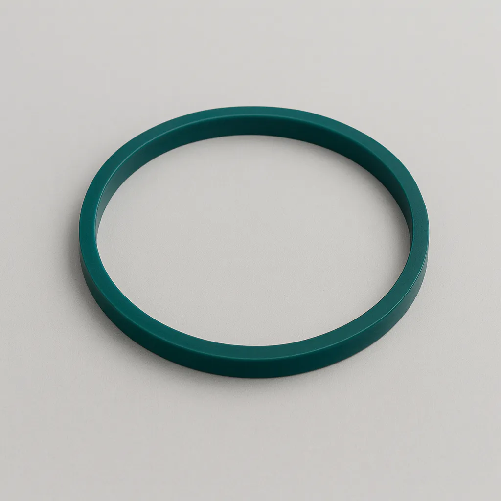
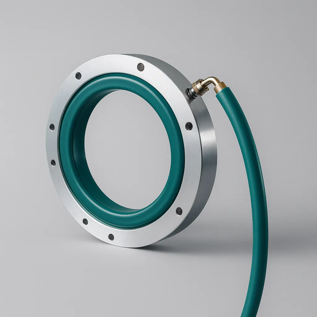
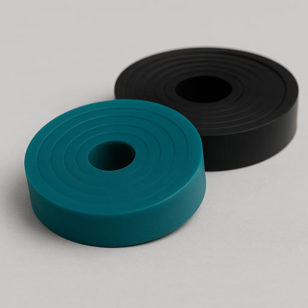
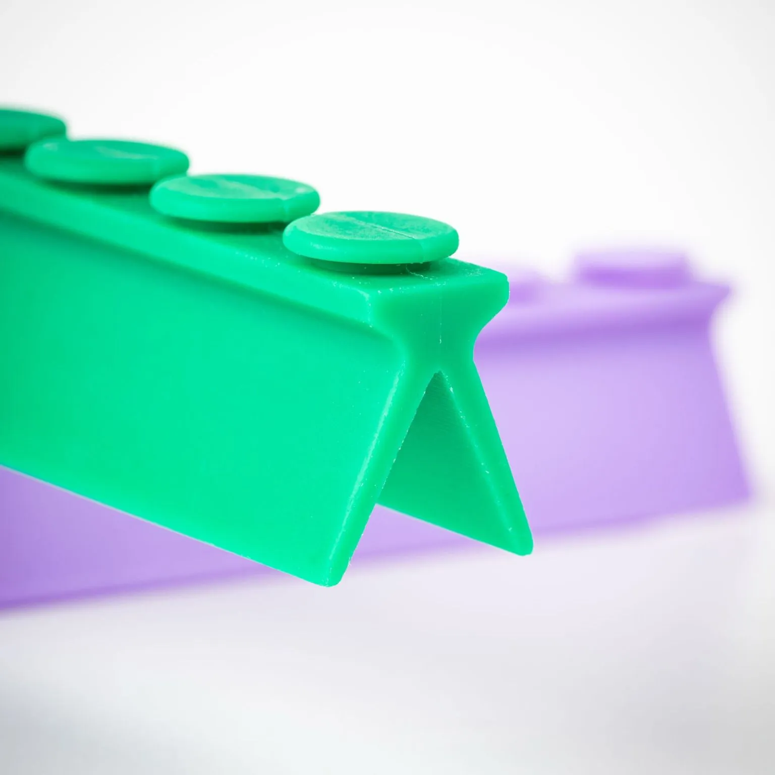
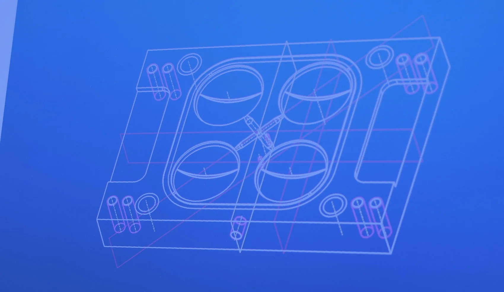
The customer's part is modelled in 3D and reworked under manufacturing constraints: draft angles, expected thermal shrinkage, minimum radii, parting lines. What the customer brings becomes what the line can run.
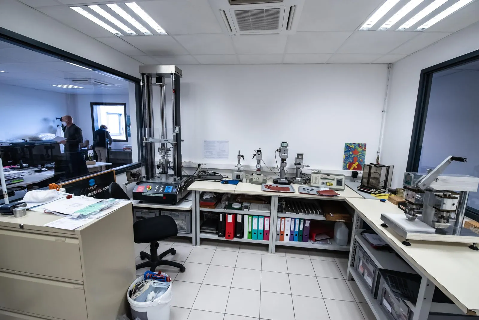
CAD design, in-house tooling machining, mixing and colour matching in our own laboratory and mechanical validation under extensometer. The drawing that arrives at the workshop is industrialised before machining starts.
2D and 3D CAD product design, design-for-manufacturing rework, mould or die machining in the integrated mechanical workshop, mixing and colour matching in our own laboratory, dimensional and mechanical validation under extensometer and micrometer. Once the sample is approved, the production line starts up with technical sheet and certificate of conformity ready.

We work with the drawing the customer brings — whether it's a clean 3D model or a hand-drawn sketch. The team industrialises the part, draws the mould or die and hands the adjoining mechanical workshop the documentation for machining. No external supplier, no file transfer.
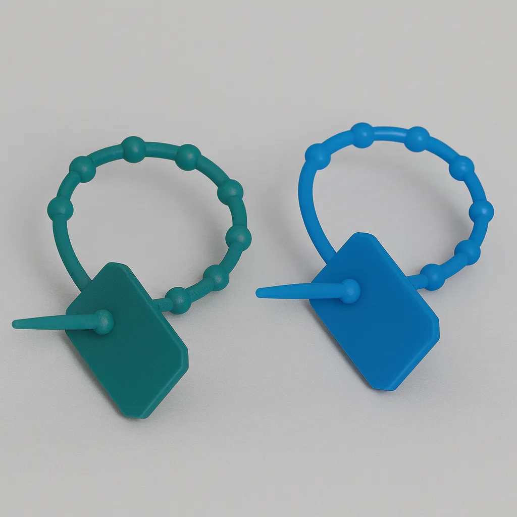
Four disciplines converge in the same plant. The part arrives as a sketch and leaves the workshop with machined tooling, matched colour and validated mechanical sheet.
The customer's part is modelled in 3D and reworked under manufacturing constraints: draft angles, expected thermal shrinkage, minimum radii, parting lines. What the customer brings becomes what the line can run.
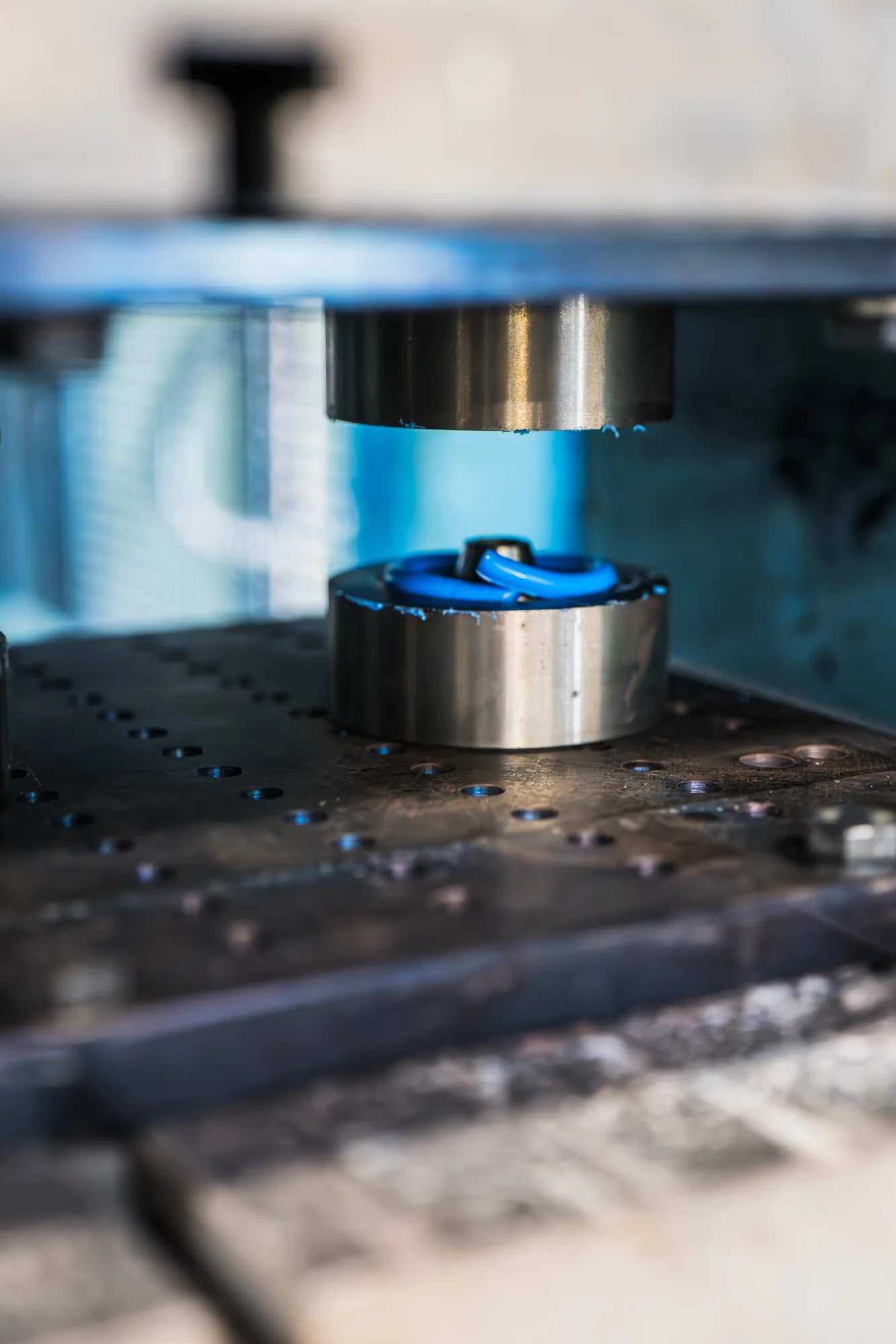
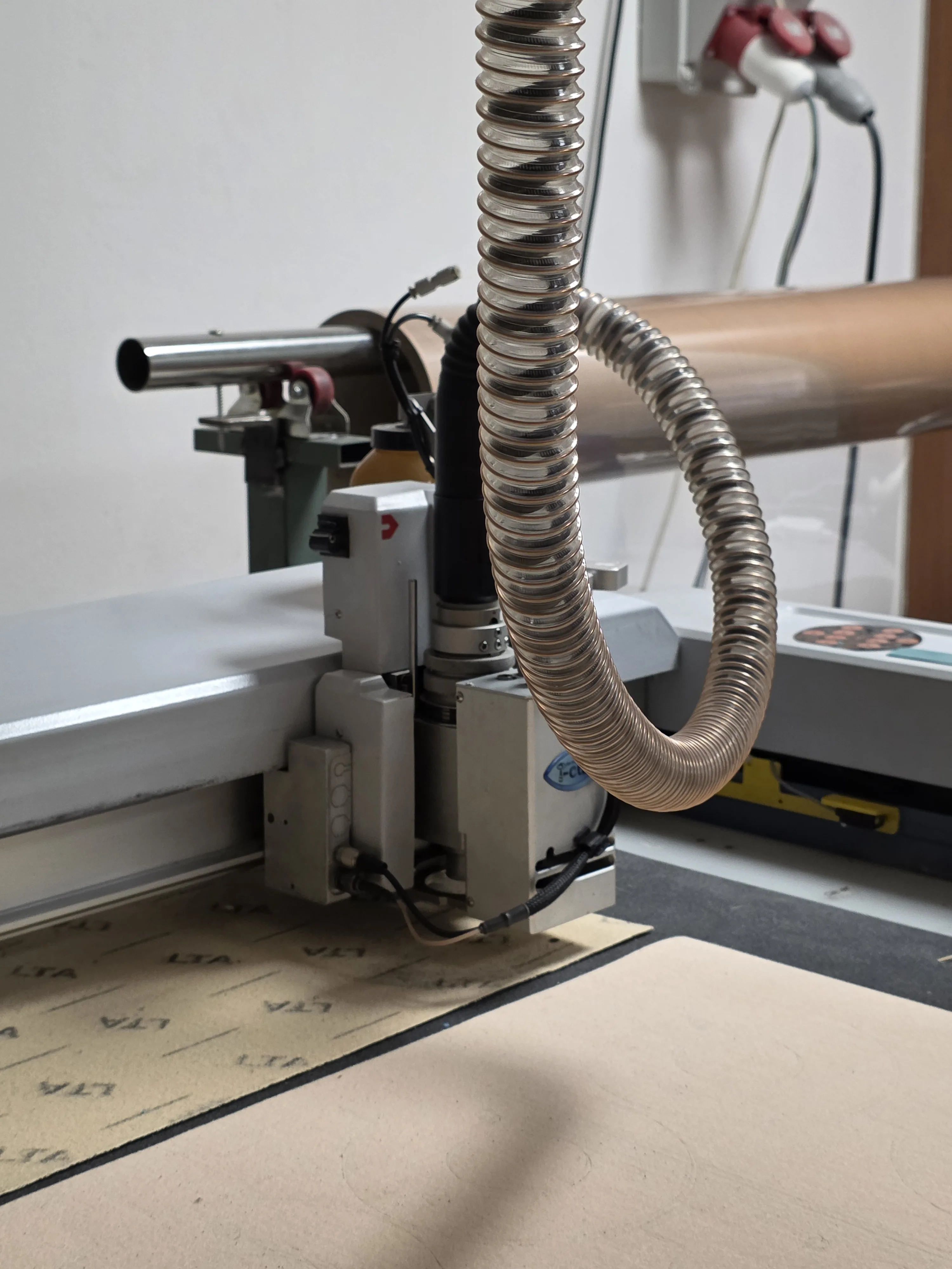
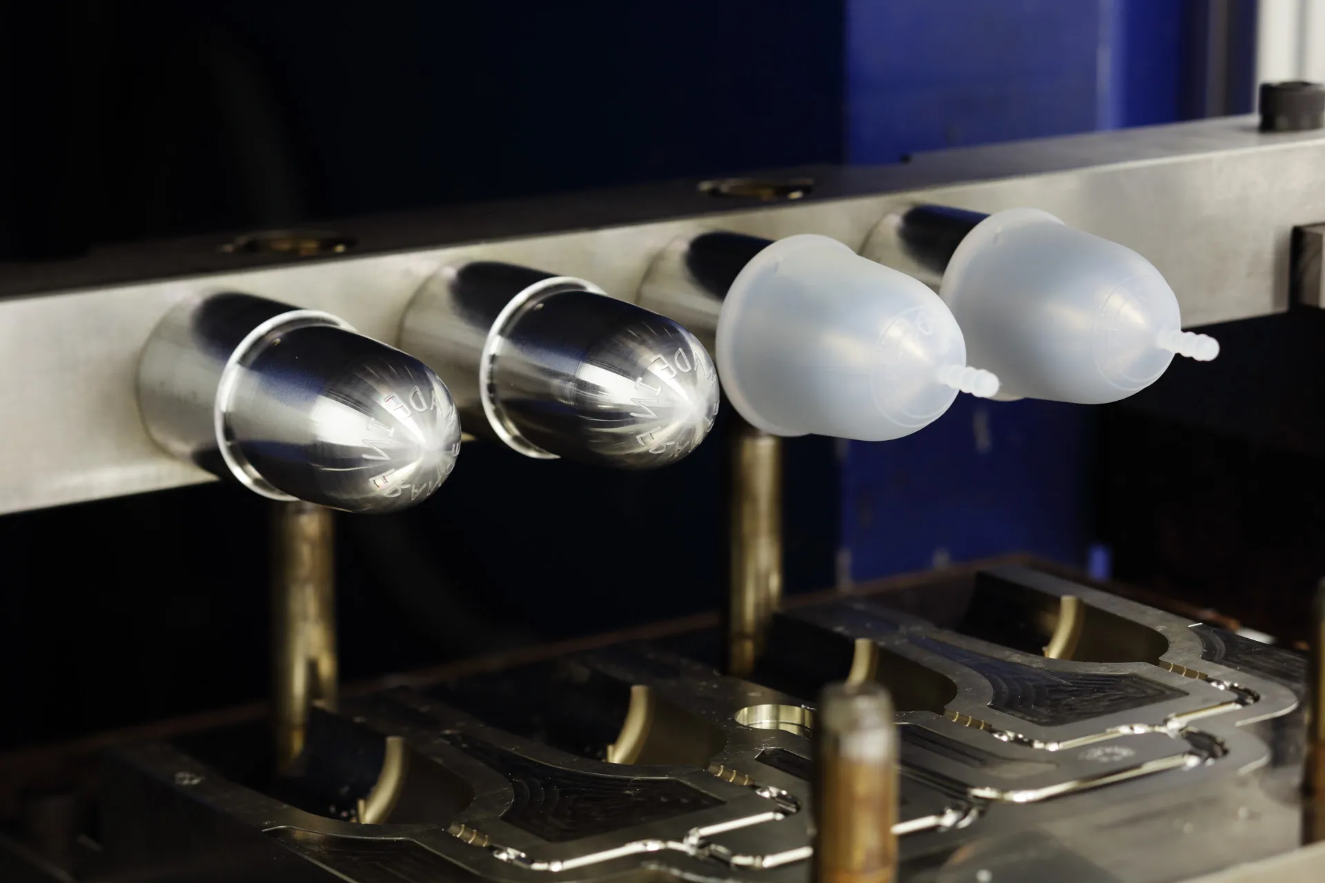
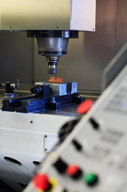
Moulds, dies, bonding moulds and cutting tools machined by turning, milling and surface finishing in our own workshop. Lead time and revisions controlled without an external supplier.
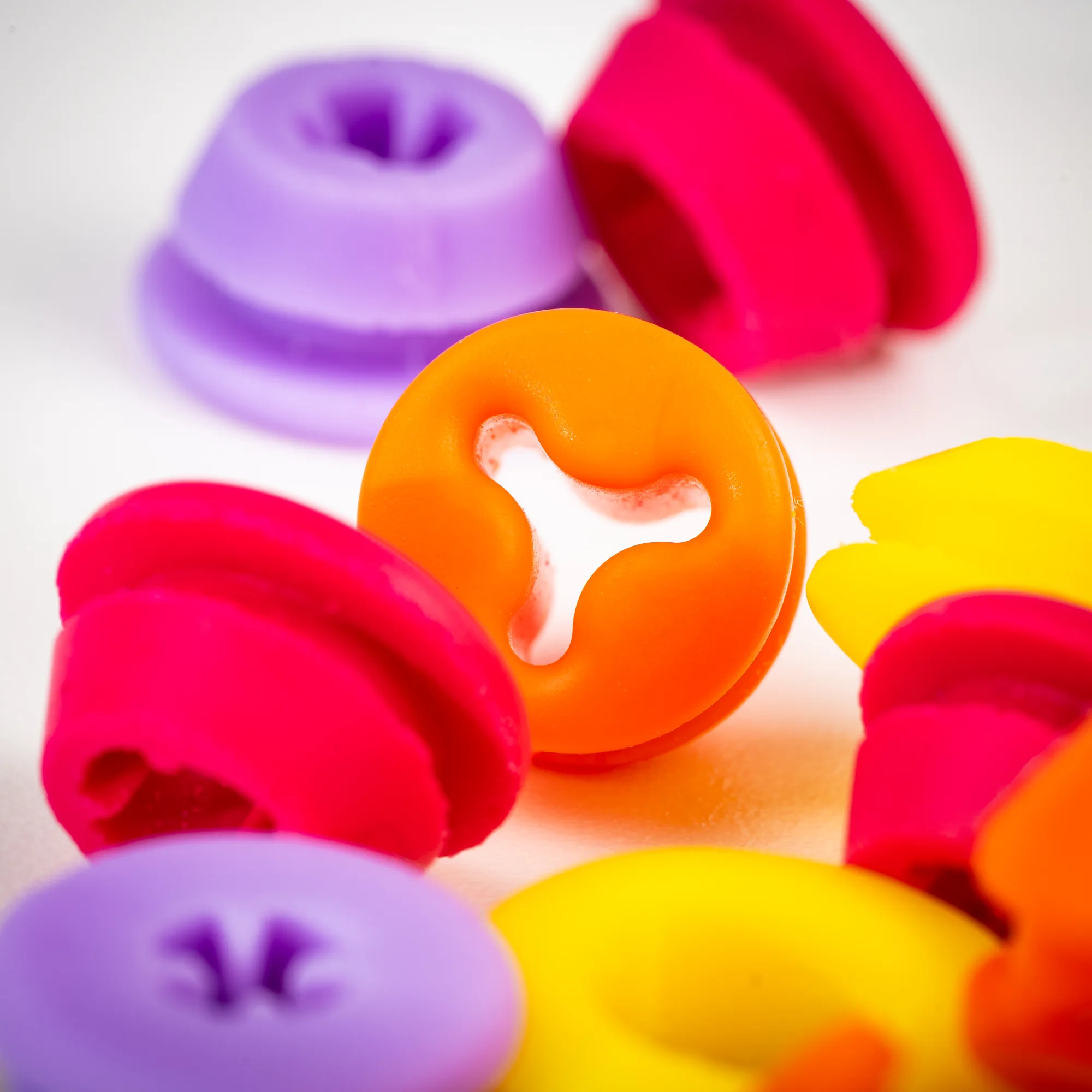
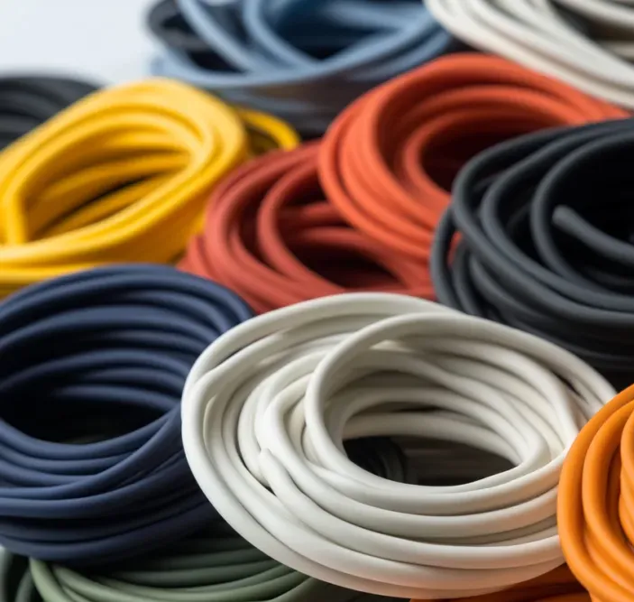
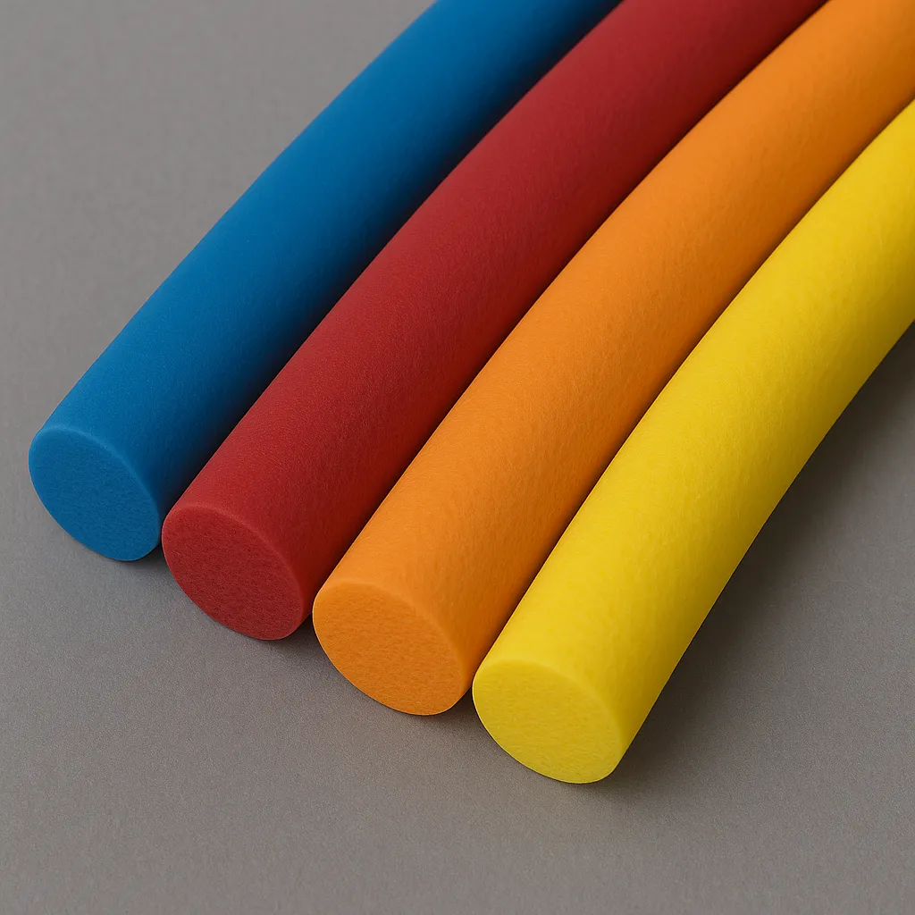
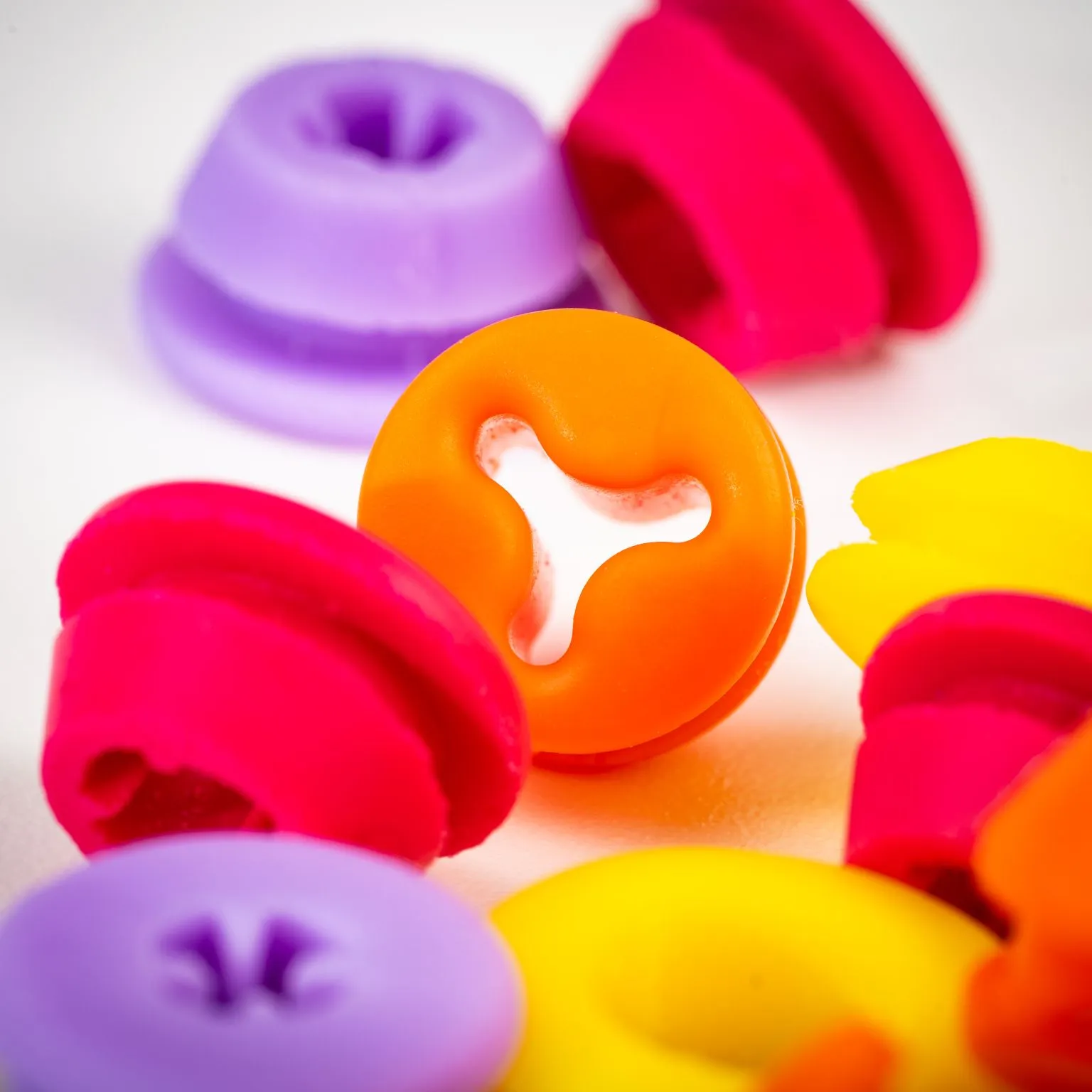
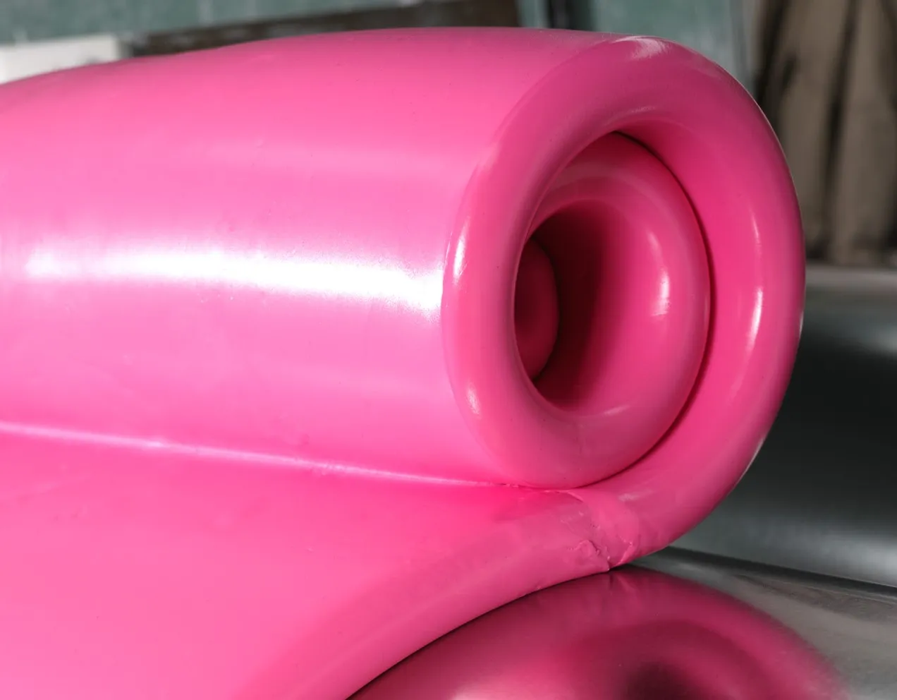
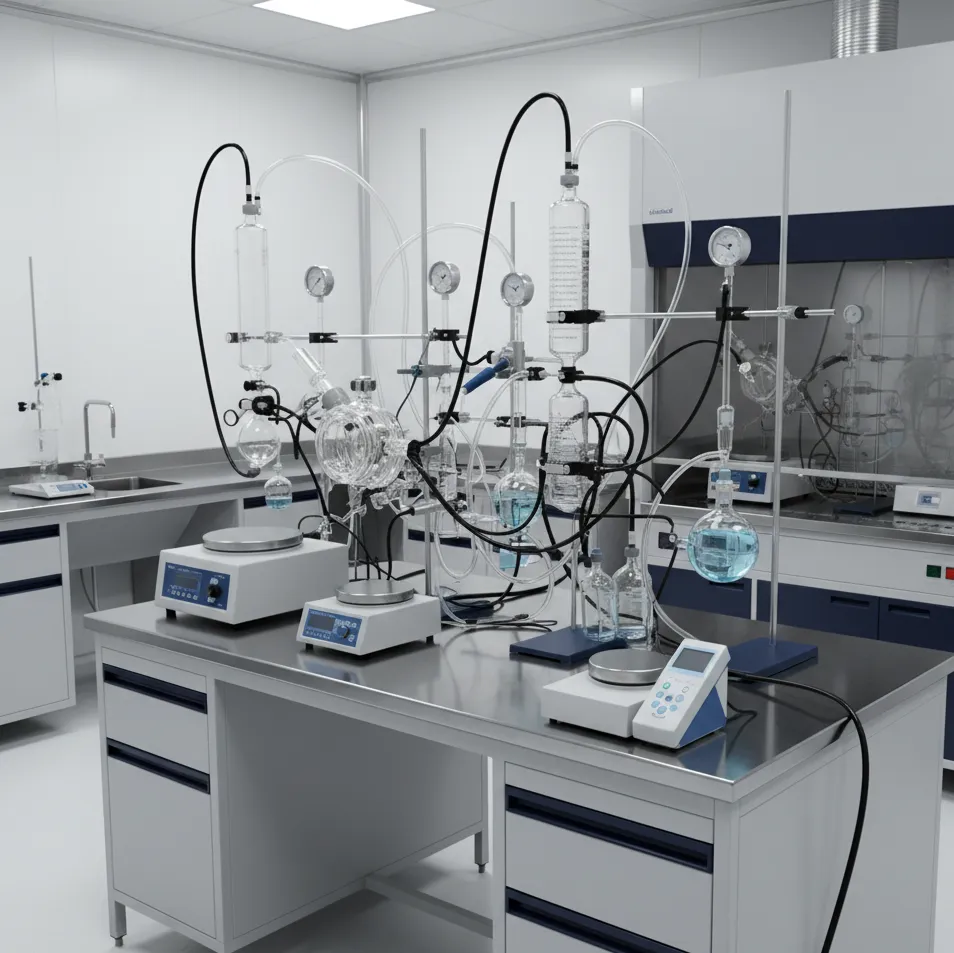
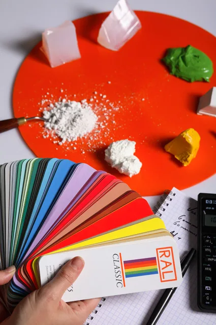
More than 500 formulas available in stock. Matching against RAL chart and Minolta spectrophotometer. Mass pigmentation before extrusion or moulding · no post-painting.
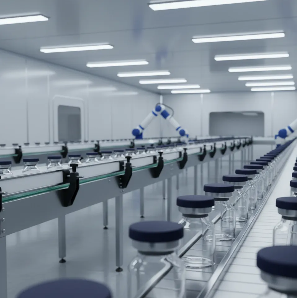
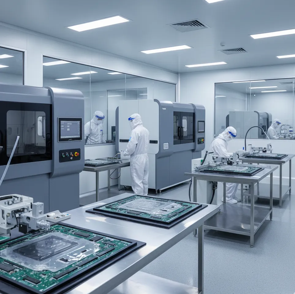
Tensile extensometer, Shore A and IRHD durometers, Mitutoyo micrometers and analytical balance. The initial sample is measured dimension by dimension before the run is approved.
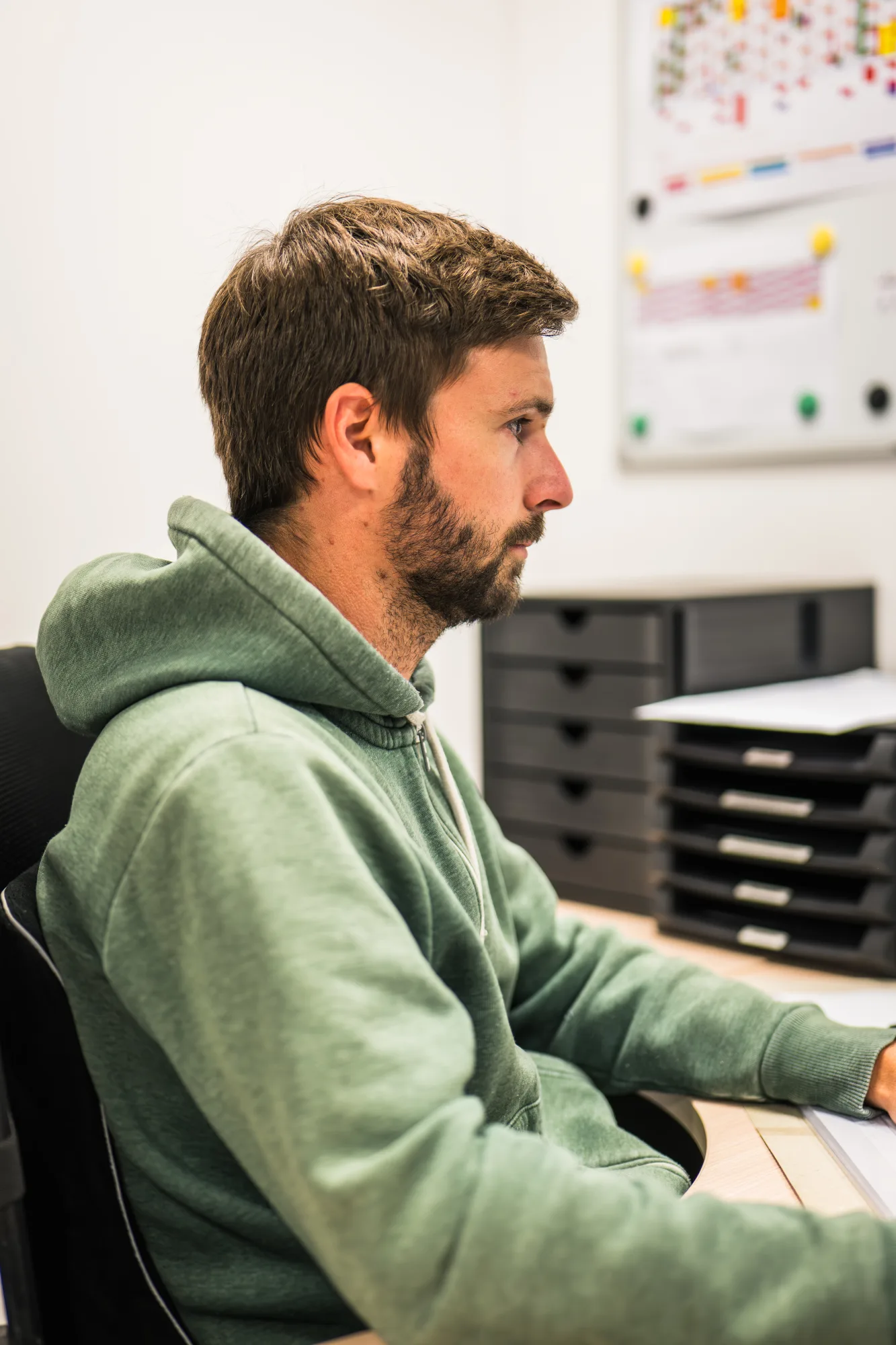
Verified figures from the design fleet and the integrated mechanical workshop. The part never leaves the site for tooling.
| Capability | Detail |
|---|---|
| CAD software | 2D and 3D · product and tooling modelling |
| Accepted formats | STL · STEP · IGES · DXF · DWG · PDF |
| Team | 7 technical specialists in the design office |
| Drawings issued per year | +1000 with revision traceability |
| Available compounds | +500 formulations in stock with pigmentation datasheet |
| Silicone families | +30 compounds: VMQ · HCR · LSR · FVMQ · conductive · cellular foam |
| Tooling types | Moulds · dies · bonding moulds · cutting tools |
| Integrated machining | Turning · milling · surface finishing · in-house workshop (Luberon) |
| Colour matching | RAL chart · Minolta spectrophotometer · mass pigmentation |
| Dimensional validation | Extensometer · Shore A and IRHD durometers · Mitutoyo micrometers · analytical balance |
| Sample lead times | Confirmed case by case according to tooling complexity and volume |
| Certification | ISO 9001 QMS |
The stages overlap depending on complexity: a simple tooling can enter machining while the design is still validating dimensions; a complex one demands closing the CAD before touching the milling machine.
Technical review of the 3D model or sketch, identification of critical tolerances and manufacturing constraints. If dimensions are missing, we define them with the customer before quoting tooling.
Design-for-manufacturing rework: draft angles, expected thermal shrinkage by material, position of parting lines, air vents, minimum thicknesses compatible with the destination line.
Full 3D modelling of the mould or die: cavities, runners, ejection system, cooling and venting. Documentation ready to hand over to the mechanical workshop.
The tooling goes through turning, milling and surface finishing in the adjoining building. No external supplier, no file transfer. Lead times and revisions controlled in-house.
First short run. Measured with extensometer, durometer and micrometer. If a critical dimension is out, the die is adjusted and the sample is repeated before the run is approved.
Once the sample is approved, definitive parameters are set. The production run leaves with technical sheet and certificate of conformity batch by batch.
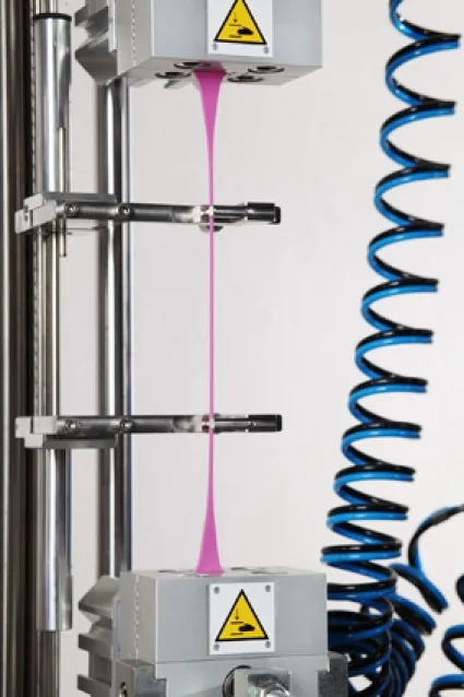
Before the sample is approved, the silicone is put through a tensile test: a standardised specimen is stretched to break. Shore A hardness, tensile strength, elongation at break, 100 % modulus and break energy are recorded in the lot's technical sheet.
This mechanical characterisation confirms that the compound meets the customer's specifications and the sector's requirements — medical, rail, food, automotive. The sheet travels with every lot produced and is kept for audits.
Send us the drawing or sketch, critical dimensions, sector, standard and estimated run size. If you need a specific RAL colour, a filled formula or validation to a sector standard, we confirm tooling lead time, applicable mix and the line assigned to the run.